
Electrical Fuses Blog
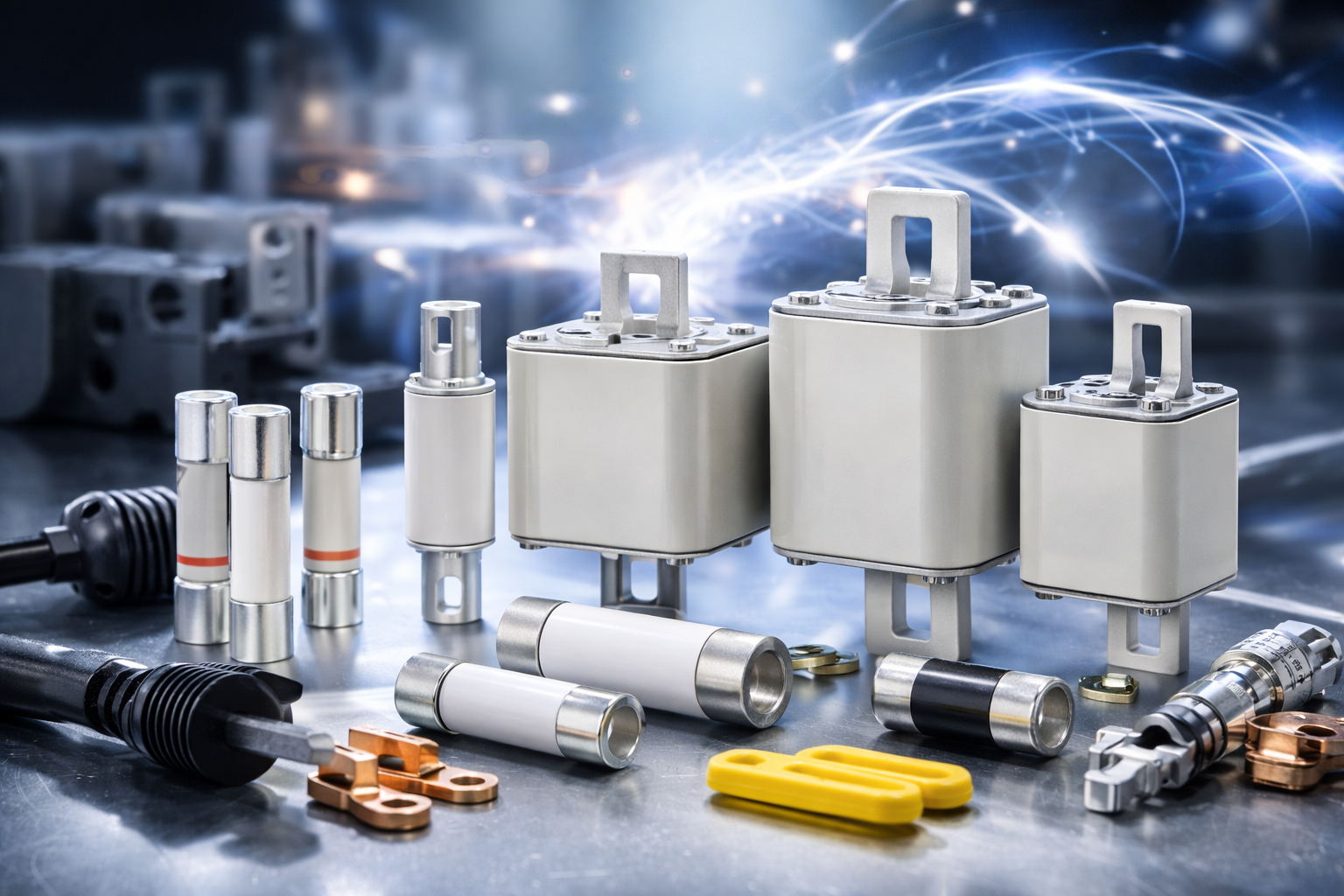
Eaton Bussmann Series Electrical Fuses – Blog & Fachwissen
Im Eaton Bussmann Series Electrical Fuses Blog finden Sie fundiertes Fachwissen rund um elektrische Sicherungen, Überstromschutz und moderne Schutzkonzepte für industrielle und gewerbliche Anwendungen. Diese Kategorie bündelt alle Blogartikel, technischen Beiträge und Praxisguides zu den Sicherungssystemen und Serien von Eaton Bussmann.
Eaton Bussmann zählt weltweit zu den führenden Herstellern von elektrischen Sicherungen, und ihre Serien stehen für Sicherheit, Normkonformität und höchste Zuverlässigkeit in anspruchsvollen elektrischen Systemen.
Was Sie im Eaton Bussmann Sicherungen Blog erwartet
Unsere Blogbeiträge helfen Ingenieuren, Einkäufern, Technikern und Planern dabei, die richtige Sicherungslösung zu finden und technische Zusammenhänge besser zu verstehen.
Themenschwerpunkte dieser Kategorie:
-
🔌 Überblick über Eaton Bussmann Sicherungsserien
-
⚙️ Unterschiede zwischen UL-, IEC- und Spezial-Sicherungen
-
📘 Technische Erklärungen zu Kennlinien, Auslöseverhalten & Bemessungswerten
-
🏭 Anwendungstipps für Industrie, Maschinenbau & Energieverteilung
-
🚗 Beiträge zu EV-, DC- und Hochvolt-Sicherungen
-
🛠 Best Practices für Auswahl, Installation und Wartung
Alle Inhalte sind praxisnah, verständlich aufbereitet und technisch fundiert.
Eaton Bussmann Sicherungsserien im Fokus
Der Blog behandelt regelmäßig verschiedene Eaton Bussmann Series Electrical Fuses, darunter:
-
Industrial Fuses
-
North American (UL) Fuse Series
-
IEC Sicherungsserien
-
High Speed & Semiconductor Fuses
-
EV & DC Sicherungen
-
Supplementary & Specialty Fuses
So erhalten Sie einen umfassenden Überblick über das Eaton Bussmann Portfolio und dessen Einsatzmöglichkeiten.
Fachwissen für sichere elektrische Systeme
Elektrische Sicherungen sind ein zentraler Bestandteil jeder sicheren Stromversorgung. Der Eaton Bussmann Series Electrical Fuses Blog unterstützt Sie dabei, Risiken zu minimieren, Normen einzuhalten und die Lebensdauer Ihrer Anlagen zu verlängern.
Ganz gleich, ob Sie Grundlagenwissen suchen oder tief in spezielle Sicherungsserien eintauchen möchten – hier finden Sie relevante, aktuelle und suchmaschinenoptimierte Inhalte rund um Eaton Bussmann Electrical Fuses.
👉 Jetzt Blogartikel entdecken und Ihr Wissen über Eaton Bussmann Sicherungsserien gezielt erweitern.
- Details
- Category: Electrical Fuses Blog
 eaton-ev-fuse-catalogue-emob0062-en-us.pdf  | [Eaton Bussmann EV Fuses] | 0 kB |
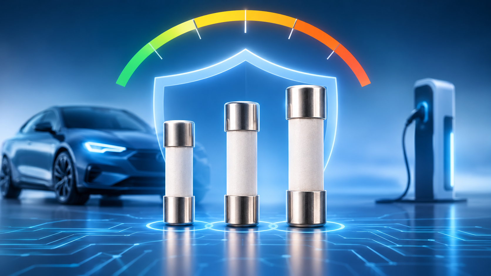
500V vs 800V vs 1000V EV Fuse: Which One Should You Choose?
Introduction
As electric vehicle technology continues to evolve, electrical system voltage is becoming an increasingly important factor in vehicle design. Modern electric vehicles are moving beyond traditional 400V architectures towards 800V and even 1000V high-voltage systems. This shift improves charging performance, energy efficiency, and power delivery while creating new requirements for electrical protection components.
One of the most important components in an EV's high-voltage protection system is the electric vehicle fuse. Selecting the correct fuse voltage rating is essential for protecting batteries, inverters, motors, charging systems, and other high-voltage electrical components against short circuits and overcurrent conditions.
But when comparing a 500V vs 800V vs 1000V EV fuse, which one is the right choice?
The answer depends on the vehicle's operating voltage, maximum system voltage, fault conditions, circuit design, and safety requirements. In this guide, we will explore the differences between these three fuse ratings, their applications, advantages, and the key factors to consider when choosing the right EV fuse.
1. Understanding EV Fuse Voltage Ratings
An electric vehicle fuse is a protective device designed to interrupt excessive electrical current when a short circuit or overload occurs. It helps prevent damage to expensive electrical components and reduces the risk of overheating, electrical fires, and system failures.
The voltage rating of a fuse indicates the maximum voltage at which it can safely interrupt an electrical fault under specified operating conditions.
Unlike current ratings, voltage ratings cannot be selected based only on normal operating requirements. A fuse must be capable of extinguishing the electrical arc generated when the fuse element melts and interrupts current.
This is particularly important in electric vehicles because their high-voltage battery systems can deliver extremely high fault currents.
The three common voltage categories considered in EV applications include:
-
500V EV Fuse: Suitable for certain lower-voltage high-power electrical architectures.
-
800V EV Fuse: Designed for high-voltage EV platforms operating around an 800V architecture.
-
1000V EV Fuse: Provides a higher voltage interruption capability for suitable high-voltage applications.
It is important to understand that a fuse's voltage rating must meet or exceed the maximum voltage it may encounter during fault interruption, not simply the nominal battery voltage.
2. 500V vs 800V vs 1000V EV Fuse: Key Differences
Although these three fuse ratings serve the same fundamental purpose, they differ in their suitability for various electric vehicle electrical architectures.
500V EV Fuse
A 500V EV fuse is generally associated with lower-voltage high-power electrical systems. It may be suitable for EV applications with nominal battery voltages below its rated interruption voltage, provided the maximum operating voltage and fault conditions remain within the fuse specifications.
Key characteristics:
-
Suitable for compatible lower-voltage EV architectures.
-
Can provide protection for battery and power distribution circuits.
-
May be used in selected auxiliary and high-power electrical applications.
-
Requires careful consideration of maximum system voltage.
-
Must have adequate DC breaking capacity for the application.
Typical applications:
-
Certain 400V-class electric vehicle platforms.
-
Battery protection circuits.
-
Power distribution units.
-
Compatible DC electrical subsystems.
The main advantage of a 500V fuse is that it can provide an appropriate protection solution for systems designed around its electrical ratings. However, it should not be used in an 800V-class system unless its specified voltage and interruption capabilities are demonstrably sufficient.
800V EV Fuse
An 800V EV fuse is designed for applications requiring higher-voltage DC circuit protection. With the growing adoption of 800V electric vehicle architectures, these fuses are becoming increasingly important in modern EV power systems.
Compared with traditional 400V-class platforms, 800V architectures can transfer the same amount of power at lower current levels. This can reduce resistive losses and support more efficient power transmission.
Key characteristics:
-
Designed for compatible high-voltage DC applications.
-
Supports 800V-class EV electrical architectures.
-
Provides protection for high-voltage battery systems.
-
Can be used in suitable charging and power distribution circuits.
-
Requires appropriate DC interruption and arc-extinguishing performance.
Typical applications:
-
800V electric vehicle battery packs.
-
High-voltage power distribution units.
-
Traction inverter protection.
-
DC charging circuits.
-
High-voltage power conversion systems.
One of the major advantages of an 800V EV fuse is its compatibility with modern high-voltage vehicle platforms. However, engineers must still verify the maximum system voltage, transient conditions, breaking capacity, and temperature performance before selecting a specific fuse.
1000V EV Fuse
A 1000V EV fuse is designed for applications that require a higher DC voltage rating. It can provide additional voltage-rating headroom for compatible high-voltage systems and applications where the maximum circuit voltage exceeds the capabilities of lower-rated fuses.
Key characteristics:
-
Suitable for applications requiring up to 1000V DC protection, within specified conditions.
-
Supports compatible high-voltage battery and power electronics systems.
-
Offers greater voltage-rating headroom than 500V and 800V alternatives.
-
Requires suitable breaking capacity and arc-quenching performance.
-
Can support selected high-voltage charging and energy storage applications.
Typical applications:
-
High-voltage EV battery systems.
-
Electric commercial vehicles.
-
High-voltage charging equipment.
-
Battery energy storage systems.
-
DC power distribution systems.
The main advantage of a 1000V EV fuse is its higher rated voltage capability. However, a higher voltage rating does not automatically make a fuse the best choice. Its current rating, breaking capacity, dimensions, thermal characteristics, and coordination with other protection devices must also match the application.
3. Comparison Table: 500V vs 800V vs 1000V EV Fuse
The following table provides a simplified comparison of the three voltage ratings.
| Comparison | 500V EV Fuse | 800V EV Fuse | 1000V EV Fuse |
|---|---|---|---|
| Voltage rating | 500V | 800V | 1000V |
| Voltage class | Lower-voltage applications | High-voltage applications | Higher-voltage applications |
| Typical suitability | Compatible 400V-class systems | Compatible 800V-class systems | Systems requiring up to 1000V protection |
| Battery protection | Yes, if properly specified | Yes, if properly specified | Yes, if properly specified |
| Charging protection | Application-dependent | Application-dependent | Application-dependent |
| Fault interruption | Depends on breaking capacity | Depends on breaking capacity | Depends on breaking capacity |
| Selection priority | System voltage and fault current | System voltage and fault current | System voltage and fault current |
Important: This comparison describes voltage categories rather than universal product specifications. Actual fuse suitability depends on the manufacturer's rated DC voltage, current rating, breaking capacity, time-current characteristics, and test conditions.
4. Why Are 800V and 1000V EV Electrical Systems Becoming More Important?
The development of higher-voltage electric vehicle architectures is driven by the demand for faster charging, improved efficiency, and higher power performance.
Faster Charging Performance
Charging speed depends on several factors, including charging power, battery characteristics, temperature, and charging infrastructure.
For a given power level, increasing system voltage reduces the current required.
For example:
-
At 400V, a 200kW system requires approximately 500A.
-
At 800V, the same 200kW power level requires approximately 250A.
This reduction in current can help reduce resistive heating and electrical losses in conductors and other components.
Improved Energy Efficiency
Electrical resistance produces heat when current flows through a circuit. These losses are proportional to the square of the current.
The relationship is expressed as:
Power Loss = I² × R
Where:
-
I = Electrical current.
-
R = Electrical resistance.
By increasing voltage and reducing current for the same power output, engineers can reduce resistive losses, assuming comparable circuit resistance.
Reduced Cable Size and Weight
Higher-voltage architectures can reduce the current required to deliver the same power. This may allow smaller or lighter conductors, depending on thermal limits, insulation requirements, mechanical design, and applicable safety standards.
Reducing cable weight can contribute to improved vehicle efficiency and packaging flexibility.
Higher Power Capability
High-voltage electrical architectures support the delivery of substantial power to traction motors, inverters, and charging systems.
However, higher voltage also increases insulation and electrical protection requirements. This makes correctly specified high-voltage fuses essential for EV safety.
5. How to Choose the Right EV Fuse Voltage Rating
Choosing between a 500V, 800V, and 1000V EV fuse requires more than comparing nominal voltage values. Engineers should evaluate the complete electrical operating environment.
1. Check the Maximum System Voltage
The first step is to identify the maximum voltage of the battery system, including its highest state-of-charge voltage and relevant operating conditions.
A battery described as a 400V system may operate above 400V when fully charged. Similarly, an 800V-class battery may have a maximum voltage significantly higher than its nominal value.
The selected fuse must have a DC voltage rating suitable for the maximum voltage that can occur across it during interruption.
2. Determine the Required Current Rating
The fuse's current rating must accommodate the circuit's normal operating current while providing protection against excessive current.
Consider:
-
Continuous operating current.
-
Peak current during acceleration.
-
Charging current.
-
Temporary overload conditions.
-
Ambient temperature.
-
Installation and cooling conditions.
A fuse with an unsuitable current rating may cause unwanted interruptions or fail to provide the required protection.
3. Evaluate DC Breaking Capacity
Breaking capacity is one of the most critical specifications when selecting an EV fuse.
It represents the maximum prospective fault current that the fuse can safely interrupt under its specified test conditions.
Because EV battery packs can deliver very high short-circuit currents, the fuse must have sufficient DC breaking capacity for the application.
A fuse with an appropriate voltage rating but insufficient breaking capacity may not provide adequate protection.
4. Consider Time-Current Characteristics
EV electrical circuits experience different current profiles during normal operation.
For example, traction systems may experience short-duration current peaks during acceleration, while charging circuits may carry relatively steady currents for extended periods.
The fuse's time-current characteristics must distinguish between acceptable temporary current increases and genuine fault conditions.
5. Check Temperature Performance
Temperature has a direct impact on fuse performance.
High ambient temperatures, enclosed installation spaces, poor ventilation, and continuous high-current operation can increase the temperature of the fuse.
Engineers should evaluate:
-
Operating temperature range.
-
Temperature derating.
-
Contact resistance.
-
Heat dissipation.
-
Mounting orientation.
-
Thermal interaction with nearby components.
6. Verify Standards and Certification Requirements
EV fuses should meet the relevant automotive and electrical safety requirements for their intended application.
Depending on the vehicle and circuit design, engineers may need to consider applicable requirements for high-voltage protection, fuse performance, environmental durability, and electrical safety.
Compliance should be verified using the actual product documentation and test reports rather than relying on the voltage rating alone.
6. Can an 800V EV Fuse Be Used in a 400V System?
In principle, an 800V-rated fuse can be used in a 400V system if its other electrical and mechanical specifications are suitable.
A higher voltage rating does not automatically create a problem in a lower-voltage circuit. However, engineers must check the fuse's current rating, DC interruption characteristics, breaking capacity, physical dimensions, and coordination with the rest of the protection system.
It is also important to consider whether the selected fuse provides appropriate protection at the system's actual operating current and fault levels.
Therefore, an 800V EV fuse may be suitable for a 400V application, but the decision should be based on the complete electrical specifications.
7. Can a 500V EV Fuse Be Used in an 800V System?
Generally, no.
A 500V-rated fuse should not be used in an 800V-class system when the voltage across the fuse during fault interruption can exceed its specified DC voltage rating.
When a fuse element melts, an electrical arc forms between the separated contacts. At higher DC voltages, extinguishing this arc becomes more challenging.
If the fuse cannot safely interrupt the fault current, the electrical arc may continue, potentially resulting in equipment damage, overheating, or serious safety hazards.
For an 800V-class electrical architecture, engineers should select a fuse with a suitable DC voltage rating and verified interruption performance.
8. Is a 1000V EV Fuse Better Than an 800V EV Fuse?
Not necessarily.
A 1000V EV fuse has a higher voltage rating than an 800V EV fuse, but this does not mean it offers better protection in every application.
The correct choice depends on several factors:
-
Maximum operating voltage.
-
Required current rating.
-
Prospective short-circuit current.
-
DC breaking capacity.
-
Time-current characteristics.
-
Temperature performance.
-
Physical dimensions and mounting requirements.
-
Applicable safety standards.
For an 800V-class system, a properly specified 800V fuse may be entirely suitable if its voltage rating covers the maximum circuit voltage and its interruption performance meets the application requirements.
A 1000V-rated fuse may be preferable when the system requires a higher voltage rating, provided all other specifications are appropriate.
The goal should always be to select the correctly engineered fuse rather than simply choosing the highest available voltage rating.
9. Common Mistakes When Selecting an EV Fuse
Selecting an incorrect fuse can compromise the safety and reliability of an electric vehicle. Some common mistakes include:
Choosing based only on nominal voltage: The maximum battery voltage, rather than the nominal voltage, must guide voltage selection.
Ignoring DC breaking capacity: A fuse must safely interrupt the available short-circuit current under specified conditions.
Selecting an unsuitable current rating: The fuse must accommodate normal operating conditions while providing adequate fault protection.
Overlooking temperature derating: High temperatures can reduce the effective current-carrying capability of a fuse.
Assuming all high-voltage fuses are interchangeable: Different fuse designs have different electrical, mechanical, and thermal characteristics.
Ignoring installation requirements: Fuse dimensions, terminal connections, mounting conditions, and vibration resistance can affect long-term performance.
Avoiding these mistakes helps engineers develop safer and more reliable EV electrical protection systems.
10. Conclusion: Which EV Fuse Should You Choose?
The choice between a 500V, 800V, and 1000V EV fuse depends primarily on the electrical architecture and maximum voltage of the application.
A 500V EV fuse may be appropriate for compatible lower-voltage electrical systems. An 800V EV fuse is designed for suitable 800V-class applications, while a 1000V EV fuse provides a higher voltage rating for systems requiring that level of protection.
There is no universally best option. The correct fuse must provide sufficient voltage withstand and DC interruption capability while matching the circuit's current requirements, fault levels, thermal conditions, and installation constraints.
Before making a final selection, always review the complete technical datasheet and verify that the fuse meets the electrical and safety requirements of the intended application.
Ultimately, choosing the right EV fuse is not simply about selecting 500V, 800V, or 1000V. It is about ensuring reliable overcurrent protection, safe fault interruption, and long-term electrical system performance.
Frequently Asked Questions (FAQs)
1. What is the difference between a 500V and an 800V EV fuse?
The primary difference is the rated voltage at which the fuse is designed to operate and safely interrupt a fault under specified conditions. An 800V-rated fuse is intended for higher-voltage applications than a 500V-rated fuse, provided its other electrical specifications are suitable.
2. Can a 1000V fuse be used in an 800V electric vehicle?
Yes, a 1000V-rated fuse can be suitable for an 800V-class electric vehicle if its current rating, breaking capacity, time-current characteristics, physical dimensions, and other specifications meet the application requirements.
3. Why is DC breaking capacity important for EV fuses?
Electric vehicle battery systems can produce extremely high short-circuit currents. DC breaking capacity determines whether a fuse can safely interrupt the prospective fault current under its specified conditions.
4. Does a higher voltage-rated fuse provide better protection?
Not necessarily. A higher voltage rating only indicates suitability for a higher voltage under specified interruption conditions. Effective protection also depends on current rating, breaking capacity, response characteristics, and operating temperature.
5. What voltage fuse is suitable for an 800V EV battery?
A fuse with a DC voltage rating that covers the battery's maximum operating voltage and has sufficient breaking capacity for the available fault current is required. The final selection should be based on the battery specifications and the fuse manufacturer's technical documentation.
6. What factors should be considered when selecting an EV fuse?
The main factors include maximum system voltage, continuous and peak current, DC breaking capacity, time-current characteristics, temperature derating, environmental conditions, mechanical requirements, and applicable safety standards.
7. Are 1000V EV fuses suitable for electric commercial vehicles?
They can be suitable for electric commercial vehicles when the electrical system requires a compatible voltage rating and the fuse meets the vehicle's current, fault interruption, thermal, and mechanical requirements.
- Details
- Category: Electrical Fuses Blog
| eaton-ev-fuse-catalogue-emob0062-en-us.pdf | [Eaton Bussmann EV Fuses] | 0 kB |
| eaton-ev-fuse-selection-guide-elx1527-en.pdf | [Eaton Bussmann EV Fuses Technical Guide] | 0 kB |
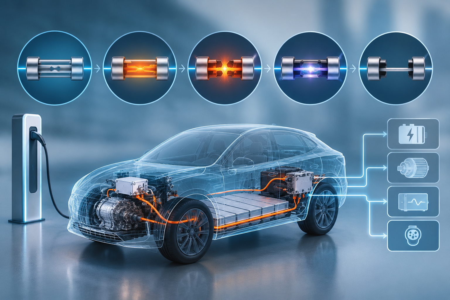
How to Select the Right EV Fuse Size? A Complete Guide
As electric vehicles (EVs) continue to evolve, electrical safety and circuit protection have become increasingly important. From high-voltage battery packs to power distribution units and auxiliary electrical systems, every circuit requires reliable overcurrent protection. Choosing the correct fuse size is essential to protect electrical components, prevent system failures and maintain the overall safety of an electric vehicle.
However, selecting the right EV fuse size involves more than simply matching the fuse's current rating to the circuit's operating current. Engineers must also consider voltage ratings, temperature conditions, short-circuit current, inrush current, breaking capacity and installation requirements.
So, how do you select the right EV fuse size?
This guide explains the key factors, calculations and practical considerations involved in choosing the appropriate fuse for electric vehicle applications.
Why Is Choosing the Correct EV Fuse Size Important?
An electric vehicle's electrical architecture contains several interconnected circuits that operate under different electrical and environmental conditions. Each circuit needs suitable protection against overloads and short circuits.
An incorrectly sized fuse can create significant safety and performance problems.
If the fuse rating is too low:
-
The fuse may blow frequently during normal vehicle operation.
-
Temporary current surges may cause unnecessary interruptions.
-
Electrical systems may experience unexpected shutdowns.
-
Maintenance requirements and operating costs may increase.
If the fuse rating is too high:
-
The fuse may fail to protect cables and electrical components effectively.
-
Excessive current may damage sensitive electronic equipment.
-
Overheating can increase the risk of electrical fires.
-
Serious short-circuit faults may cause extensive system damage.
Therefore, the correct EV fuse size must provide a balance between reliable circuit operation and effective fault protection.
1. Determine the Continuous Operating Current
The first step in selecting the right EV fuse size is identifying the maximum continuous current flowing through the circuit under normal operating conditions.
Different EV components have different current requirements. For example:
-
Battery management systems.
-
DC-DC converters.
-
Electric compressors.
-
Cooling fans and pumps.
-
Onboard chargers.
-
Power distribution units.
Suppose an auxiliary electrical circuit draws a continuous current of 35A. Selecting a 35A fuse may not provide sufficient operating margin, particularly when temperature and installation conditions affect the fuse's performance.
A preliminary sizing approach sometimes uses a 75% continuous-loading guideline:
Minimum preliminary fuse rating = Continuous operating current ÷ 0.75
For example:
35A ÷ 0.75 = 46.7A
Based on this calculation, a 50A fuse could be considered as an initial candidate.
However, this is only a preliminary estimate, not a universal EV fuse-sizing requirement. The final rating must be verified against the fuse manufacturer's operating characteristics, applicable standards, conductor ampacity and the specific circuit design.
2. Consider Ambient Temperature and Temperature Derating
Temperature is another important factor when selecting an EV fuse.
Electric vehicles operate in demanding environments where electrical components may be exposed to elevated temperatures. Battery compartments, engine compartments, power electronics enclosures and charging systems can all experience substantial temperature variations.
Fuse performance is influenced by ambient temperature because higher temperatures can reduce the additional heat a fuse element can tolerate before opening.
For example, assume a fuse has a temperature correction factor of 0.85 under a particular operating condition.
Using the previous 35A continuous-current example:
Step 1: Calculate the preliminary fuse rating.
35A ÷ 0.75 = 46.7A
Step 2: Apply the temperature correction factor.
46.7A ÷ 0.85 = 54.9A
A 60A fuse may therefore be evaluated as a potential candidate.
The actual selection must be confirmed using the manufacturer's temperature-derating data. Correction factors vary depending on fuse construction, ambient temperature, mounting arrangements and cooling conditions.
Important: Temperature derating should be evaluated together with conductor temperature limits, terminal temperature ratings and the thermal conditions inside the vehicle enclosure.
3. Match the Fuse Voltage Rating to the EV System
Voltage rating is one of the most critical considerations in EV fuse selection.
Unlike many conventional automotive electrical systems, modern electric vehicles use high-voltage DC architectures. Common system configurations include approximately 400V and 800V, although actual operating voltages vary by vehicle design.
A fuse must be specifically rated for the voltage and current conditions of the circuit it protects.
Why does this matter?
When a fuse opens, an electrical arc can form between the separated fuse elements. In AC circuits, current naturally passes through zero during each cycle, helping extinguish the arc. DC circuits do not have these regular current-zero crossings, making arc interruption more challenging.
Using an unsuitable fuse in a high-voltage DC application can therefore create serious safety risks.
Before selecting an EV fuse, verify:
-
The maximum operating voltage of the electrical system.
-
The maximum transient or charging voltage.
-
The fuse's rated DC voltage.
-
Its DC arc-interruption capability.
-
Its suitability for the specific battery or power electronics application.
Never assume that an AC-rated fuse is suitable for a DC circuit simply because the voltage values appear similar.
4. Check the Breaking Capacity of the Fuse
Breaking capacity, also known as interrupting capacity, refers to the maximum prospective fault current a fuse can safely interrupt under its specified operating conditions.
This parameter is particularly important in electric vehicles because battery packs can deliver extremely high short-circuit currents.
During a short circuit, the available fault current depends on several factors, including:
-
Battery pack voltage.
-
Internal battery resistance.
-
Cell configuration.
-
Busbar resistance.
-
Cable impedance.
-
Electrical connection resistance.
-
Battery state of charge and operating conditions.
The selected fuse must have a breaking capacity greater than the maximum prospective short-circuit current at its installation location.
For example, if the calculated prospective fault current is 15kA, a fuse with a 10kA breaking capacity would be unsuitable.
A fuse with an adequate rated breaking capacity must be selected and verified for the actual circuit conditions.
Choosing a fuse with insufficient breaking capacity can result in failure to interrupt the fault safely, potentially causing arcing, equipment damage or fire.
5. Understand Inrush Current and Time-Current Characteristics
Some EV components draw significantly higher current during startup than during normal operation.
This temporary increase is called inrush current.
It commonly occurs in:
-
Electric motors and compressors.
-
Inverters.
-
Capacitive electronic circuits.
-
DC-DC converters.
-
Charging and pre-charge circuits.
For example, a component with a normal operating current of 30A may briefly draw 90A during startup.
If the selected fuse cannot tolerate this temporary current surge, it may open unnecessarily even though the circuit is operating normally.
To avoid this problem, engineers should evaluate the fuse's time-current characteristics.
There are two common operating characteristics:
Fast-acting fuses
Fast-acting fuses respond quickly to excessive current. They are generally suitable for circuits that require rapid protection and have limited startup current.
Time-delay fuses
Time-delay fuses can tolerate specified temporary current surges without opening immediately. They may be suitable for motor-driven equipment and circuits with significant inrush current.
The correct choice depends on the magnitude, duration and frequency of the current surge, as well as the protection requirements of the connected components.
Engineers should evaluate the fuse time-current curve and verify that the fuse can withstand normal startup conditions while still providing adequate protection during overloads and short circuits.
6. Select the Appropriate Fuse Type and Physical Size
Electrical performance is not the only consideration when choosing an EV fuse. Its physical construction and mounting arrangement must also be compatible with the vehicle's electrical architecture.
Common EV fuse configurations include:
Bolt-down fuses
These are commonly used in high-current applications, including battery protection and power distribution systems. Their bolted connections provide secure electrical and mechanical mounting.
Lug-type fuses
Lug-type configurations are used in applications where specific terminal and connection arrangements are required.
PCB-mounted fuses
These are suitable for certain lower-current electronic circuits and printed circuit board applications.
Before finalising the fuse selection, check the following physical specifications:
-
Overall dimensions and available installation space.
-
Terminal type and connection arrangement.
-
Mounting hole dimensions.
-
Rated current and voltage.
-
Terminal temperature limitations.
-
Vibration and mechanical durability.
-
Compatibility with the fuse holder or busbar.
An incorrectly fitted fuse can create high-resistance connections, excessive heat generation and unreliable electrical performance.
7. Consider Circuit Coordination and Protection Requirements
An EV electrical system often contains multiple protective devices arranged across different circuit levels.
For example, a battery pack may have a main fuse, while individual downstream circuits have their own branch-circuit protection.
These protective devices should be coordinated so that a fault in one branch does not unnecessarily interrupt the entire electrical system.
When evaluating fuse coordination, consider:
-
Fuse time-current curves.
-
Prospective short-circuit current.
-
Fuse pre-arcing and total-clearing I²t values.
-
Cable withstand capability.
-
Semiconductor protection requirements.
-
Downstream component limitations.
Proper coordination helps ensure that the protective device closest to a fault operates appropriately while maintaining protection throughout the electrical system.
8. Test and Validate the Selected EV Fuse
Calculations and technical specifications provide a starting point, but real-world validation is essential before finalising an EV fuse selection.
Testing should reflect the actual operating environment and electrical characteristics of the vehicle.
Important validation procedures include:
Temperature-rise testing
Operate the circuit at its maximum expected continuous load under representative worst-case ambient and installation conditions. Confirm that fuse, terminal and connection temperatures remain within their specified limits.
Inrush-current testing
Measure the startup current waveform to determine whether the fuse can withstand temporary current surges without unnecessary operation.
Overload testing
Verify that the fuse operates within its specified time-current characteristics under defined overload conditions.
Short-circuit testing
Confirm that the fuse can safely interrupt the expected fault current at the applicable DC voltage.
Vibration and mechanical testing
Evaluate the mechanical reliability of the fuse and its connections under vehicle operating conditions.
Testing should be conducted using appropriate engineering procedures, equipment and applicable safety standards.
Common Mistakes to Avoid When Selecting EV Fuse Size
Even a seemingly minor mistake in fuse selection can affect the safety and reliability of an electric vehicle.
Here are some common mistakes engineers should avoid:
| Common mistake | Potential consequence | Recommended approach |
|---|---|---|
| Selecting a fuse based only on normal operating current | Unnecessary fuse operation | Evaluate continuous loading and operating conditions |
| Ignoring temperature derating | Premature fuse opening | Apply manufacturer-specific temperature correction |
| Using an unsuitable AC-rated fuse in a DC circuit | Unsafe arc interruption | Verify the fuse's DC voltage rating |
| Ignoring inrush current | Startup-related interruptions | Evaluate time-current characteristics |
| Choosing insufficient breaking capacity | Failure to interrupt fault current safely | Calculate prospective short-circuit current |
| Oversizing the fuse | Inadequate circuit protection | Check cable and component protection requirements |
| Ignoring physical compatibility | Overheating or unreliable connections | Verify terminals and mounting dimensions |
Avoiding these mistakes can improve electrical protection, system reliability and long-term EV performance.
Advanced Considerations for Modern Electric Vehicle Systems
As EV technology advances, electrical protection requirements are becoming increasingly sophisticated.
Several developments deserve particular attention.
800V EV architectures
Higher-voltage battery systems require appropriately rated high-voltage DC fuses. Engineers must evaluate maximum system voltage, transient conditions, arc interruption and insulation requirements.
Advanced power electronics
Modern inverters and converters use high-speed semiconductor switching technologies. Their protection requirements may involve specific current-limiting and energy-coordination characteristics.
Bidirectional charging
Vehicle-to-grid and vehicle-to-home applications allow electrical energy to flow in different directions. Fuse suitability must be verified for the actual current paths and fault conditions.
Battery energy storage integration
EV battery systems and associated energy storage applications require careful coordination between battery protection, power conversion and distribution circuits.
These developments make application-specific fuse selection increasingly important.
EV Fuse Selection Checklist
Before choosing an EV fuse, use the following checklist to review the most important technical parameters:
-
Identify the maximum continuous operating current.
-
Determine the expected peak and inrush current.
-
Calculate the maximum prospective short-circuit current.
-
Verify the required DC voltage rating.
-
Check the fuse breaking capacity.
-
Apply the appropriate temperature derating factors.
-
Review time-current characteristics.
-
Confirm cable and component protection requirements.
-
Check fuse dimensions and terminal compatibility.
-
Evaluate vibration and environmental conditions.
-
Verify coordination with other protective devices.
-
Conduct appropriate electrical and thermal validation tests.
Following this checklist helps engineers make a more informed and reliable fuse selection.
Frequently Asked Questions About EV Fuse Sizing
1. How do I calculate the correct EV fuse size?
Start by determining the maximum continuous current flowing through the circuit. Then evaluate temperature derating, inrush current, voltage rating, breaking capacity and conductor protection requirements.
A preliminary calculation may use:
Minimum preliminary fuse rating = Continuous current ÷ 0.75
However, the final fuse rating must be validated against the manufacturer's specifications and the actual electrical protection requirements.
2. Can I use a standard automotive fuse in an electric vehicle?
Not necessarily. Standard automotive fuses may have voltage and interrupting ratings that are unsuitable for high-voltage EV applications.
Always verify the fuse's DC voltage rating, breaking capacity and application suitability before installation.
3. What is the difference between a fast-acting and a time-delay EV fuse?
A fast-acting fuse responds quickly to excessive current, making it suitable for circuits requiring rapid protection.
A time-delay fuse can withstand specified temporary current surges, making it potentially suitable for motors, compressors and other circuits with high inrush current.
4. Why is breaking capacity important for EV fuses?
EV battery packs can deliver very high fault currents during short circuits. The fuse must be capable of safely interrupting the maximum prospective fault current without sustaining a dangerous arc or suffering physical failure.
5. Does temperature affect EV fuse performance?
Yes. Elevated ambient temperatures can reduce a fuse's current-carrying capability and affect its operating characteristics. Temperature derating should therefore be considered during fuse selection.
6. What voltage rating is required for an 800V EV system?
The fuse must have a DC voltage rating suitable for the system's maximum operating and transient voltage conditions. A nominal 800V system should not automatically be matched with an 800V-rated fuse. The complete voltage envelope and the fuse manufacturer's specifications must be evaluated.
7. Should I choose a higher-rated fuse to prevent frequent fuse failures?
No. Simply increasing the fuse current rating can compromise circuit protection. Frequent fuse operation should be investigated to identify possible causes, such as excessive load, startup surges, elevated temperature or electrical faults.
Conclusion
Selecting the right EV fuse size is a critical part of designing a safe and reliable electric vehicle electrical system. The process requires more than matching a fuse's current rating to the circuit's operating current.
Engineers must consider continuous current, temperature derating, DC voltage rating, breaking capacity, inrush current, time-current characteristics, physical compatibility and circuit coordination.
Most importantly, the selected fuse must provide reliable protection under both normal operating conditions and potential fault scenarios.
By following a systematic selection and validation process, engineers can minimise unnecessary fuse operation, improve electrical safety and protect essential EV components against overloads and short circuits.
Ultimately, the right EV fuse is not simply the one with the closest current rating. It is the one that meets the complete electrical, thermal, mechanical and safety requirements of its intended application.
- Details
- Category: Electrical Fuses Blog
| eaton-bussmann-series-high-speed-fuses-application-guide-br132015en-en-us.pdf | [Eaton Bussmann Fuses Technical Guide] | 0 kB |
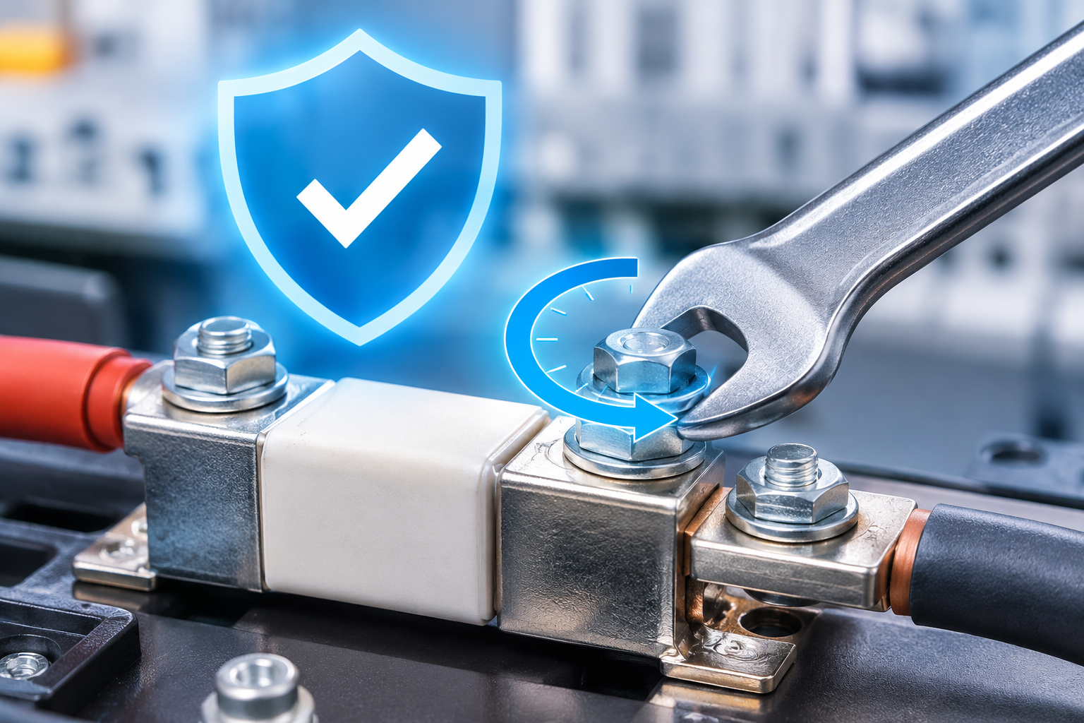
Proper Torque for M6 and M8 Fuse Bolts: Recommended Specifications and Installation Guide
Proper torque for M6 and M8 fuse bolts is essential for maintaining safe, reliable, and efficient electrical connections. In high-current electrical systems, including electric vehicles, solar power installations, battery energy storage systems, and industrial equipment, correctly tightened fuse connections help prevent overheating, voltage drops, and unexpected electrical failures.
Applying insufficient torque can result in loose connections and increased electrical resistance. Excessive tightening, on the other hand, may damage threads, deform terminals, or crack fuse housings.
So, what is the correct torque for M6 and M8 fuse bolts? The answer depends on several factors, including bolt grade, terminal material, lubrication, and the mechanical specifications of the fuse assembly.
This guide explains recommended M6 and M8 fuse bolt torque values, proper tightening procedures, common installation mistakes, and essential maintenance practices.
1. Why Is Proper Torque Important for Fuse Bolts?
Fuse bolts create both mechanical and electrical connections. Their primary purpose is to maintain sufficient contact pressure between conductive surfaces, ensuring stable current transmission.
Correct tightening torque is important for several reasons.
Prevents Electrical Overheating
Loose fuse connections increase contact resistance. When electrical current passes through a high-resistance connection, additional heat is generated.
For example, in a 200A electrical circuit, an additional contact resistance of 0.5 milliohms can generate approximately 20 watts of localized heat.
Continuous overheating can damage insulation, terminals, and surrounding components.
Ensures Stable Electrical Performance
Proper bolt torque maintains consistent contact pressure between the fuse terminal and connecting conductor.
This helps reduce voltage drops, minimize energy losses, and maintain reliable electrical performance.
Protects Fuse Terminals and Housings
Overtightening can damage threaded connections, deform metal terminals, and place excessive mechanical stress on fuse housings.
In severe cases, excessive tightening may compromise the structural integrity of the fuse assembly.
Improves Long-Term Reliability
Electrical systems frequently experience vibration, temperature changes, and thermal cycling.
Correctly installed fuse connections are better equipped to withstand these operating conditions and maintain reliable performance.
2. Recommended Torque Specifications for M6 and M8 Fuse Bolts
The appropriate tightening torque depends on bolt diameter, mechanical strength grade, surface condition, and lubrication.
The following table provides typical starting torque ranges for M6 and M8 steel bolts.
M6 and M8 Fuse Bolt Torque Chart
| Bolt Size | Bolt Grade | Lubrication Condition | Recommended Torque |
|---|---|---|---|
| M6 | 8.8 | Dry, zinc-plated | 9–11 Nm |
| M6 | 8.8 | Light oil or threadlocker | 8–10 Nm |
| M6 | 10.9 | Dry | 11–13 Nm |
| M8 | 8.8 | Dry | 20–23 Nm |
| M8 | 8.8 | Lubricated | 18–21 Nm |
| M8 | 10.9 | Dry | 23–26 Nm |
These values are general reference ranges rather than universal specifications. The fuse manufacturer's recommended tightening torque must always take priority.
M6 Fuse Bolt Torque
M6 fuse bolts are commonly used in compact electrical assemblies, including automotive electrical systems, battery connections, and smaller power distribution equipment.
For a standard grade 8.8 M6 steel bolt, a typical dry tightening torque is approximately 9–11 Nm.
When lubrication is applied, the required torque may decrease because lubrication reduces friction between the threads and contact surfaces.
For aluminium terminals, lower tightening torque may be necessary. In some applications, an M6 connection may require a maximum torque of approximately 8 Nm, depending on the terminal design.
M8 Fuse Bolt Torque
M8 fuse bolts are frequently used in higher-current electrical connections where greater mechanical strength and contact pressure are required.
For a standard grade 8.8 M8 steel bolt, a typical dry tightening torque is approximately 20–23 Nm.
Lubricated M8 connections generally require a lower torque setting.
However, some fuse assemblies have lower mechanical limits than the bolts themselves. Always check the specified torque for the complete fuse and terminal assembly.
3. Factors That Affect M6 and M8 Fuse Bolt Torque
Selecting the correct torque involves more than identifying the bolt diameter. Several technical factors influence the final tightening requirement.
Bolt Strength Grade
Bolt strength grades determine the mechanical properties of fasteners.
Common grades include:
-
Grade 8.8: Commonly used for general industrial and electrical fastening applications.
-
Grade 10.9: Offers higher tensile strength and can support higher mechanical loads.
A higher bolt strength grade does not automatically mean that a higher tightening torque is suitable for the fuse assembly. Terminal and housing limitations must also be considered.
Lubrication Conditions
Lubrication significantly affects the relationship between tightening torque and bolt preload.
A dry bolt experiences greater friction during tightening than a lubricated bolt.
Applying lubricant without adjusting the torque specification can produce excessive clamping force and potentially damage the connection.
Terminal Material
The material of the fuse terminal is another important consideration.
Copper terminals: Copper generally provides good electrical conductivity and mechanical stability.
Aluminium terminals: Aluminium requires additional attention because of its lower mechanical strength and potential creep under sustained pressure and elevated temperatures.
For aluminium connections, always follow the terminal manufacturer's torque recommendations.
Operating Temperature and Vibration
High-current electrical systems experience temperature fluctuations during normal operation.
Repeated heating and cooling can affect joint pressure. Vibration may also contribute to loosening if the connection is not properly designed and assembled.
For this reason, torque requirements should account for the actual operating environment.
4. How to Tighten M6 and M8 Fuse Bolts Correctly
Following a consistent installation procedure helps ensure reliable electrical connections and reduces the risk of mechanical damage.
Step 1: Clean the Contact Surfaces
Remove dirt, dust, oxidation, and other contaminants from the terminal and connecting surfaces.
Clean contact areas help establish a stable electrical connection.
Use cleaning products and methods suitable for the terminal material.
Step 2: Inspect the Bolt and Terminal
Before installation, inspect the bolt, threads, and terminal surfaces.
Look for:
-
Damaged or deformed threads.
-
Corrosion or oxidation.
-
Cracks in the fuse housing.
-
Bent or damaged terminals.
-
Surface contamination.
Replace damaged components before assembly.
Step 3: Check Lubrication Requirements
Determine whether the connection requires dry installation, lubricant, or a specified thread-locking compound.
Do not apply lubricant or threadlocker unless permitted by the assembly specifications.
Remember that changing the friction conditions can significantly affect the resulting clamping force.
Step 4: Start the Bolt by Hand
Carefully insert the bolt and turn it by hand to prevent cross-threading.
The bolt should rotate smoothly without unusual resistance.
Cross-threading can damage the terminal and create an unreliable mechanical connection.
Step 5: Use a Calibrated Torque Wrench
Select a calibrated torque wrench with an appropriate operating range.
Set the wrench according to the specified torque value for the complete fuse assembly.
Avoid using an impact wrench for final tightening because it does not provide sufficiently controlled torque application.
Step 6: Tighten Gradually
Where the assembly instructions permit, tighten the bolt in stages.
A typical approach is to apply approximately 50% of the target torque initially, followed by the specified final torque.
Apply steady pressure and avoid sudden movements.
Step 7: Perform a Final Inspection
After tightening, inspect the connection for proper alignment and mechanical stability.
Do not repeatedly tighten the bolt after reaching the specified torque.
If the connection requires verification, follow the approved inspection procedure.
5. Common Mistakes When Tightening Fuse Bolts
Even experienced technicians can make mistakes during fuse installation. Understanding these problems helps improve electrical safety and assembly quality.
Using Incorrect Torque Values
Applying a generic bolt torque chart without considering the fuse manufacturer's specifications is a common mistake.
The mechanical strength of a bolt does not necessarily represent the maximum torque that a fuse terminal can withstand.
Tightening Without a Torque Wrench
Estimating torque by hand is unreliable, particularly for electrical connections requiring precise clamping pressure.
A calibrated torque wrench provides more consistent and repeatable results.
Ignoring Terminal Material
Copper and aluminium terminals have different mechanical properties.
Using the same torque specification for both materials can lead to insufficient clamping force or terminal damage.
Applying Excessive Lubrication
Lubrication reduces friction and changes the relationship between applied torque and bolt preload.
Using a dry-installation torque specification on a lubricated connection can result in excessive clamping force.
Ignoring Thermal Cycling
Repeated temperature changes can influence the mechanical condition of electrical connections.
Inspection and maintenance intervals should be established according to the equipment manufacturer's recommendations and the operating environment.
Using Damaged Fasteners
Corroded, stretched, or deformed bolts may not maintain the required clamping force.
Damaged fasteners should be replaced rather than reused.
6. Special Considerations for High-Current Fuse Applications
M6 and M8 fuse bolts are widely used in electrical systems where reliable current transmission and overcurrent protection are essential.
Different applications may require additional installation considerations.
Electric Vehicles
Electric vehicle electrical systems operate with high currents and demanding temperature conditions.
Fuse connections must maintain reliable electrical contact while withstanding vibration and repeated operating cycles.
Correct bolt torque helps prevent localized overheating and connection failures.
Battery Energy Storage Systems
Battery energy storage systems contain electrical connections that may operate continuously under significant loads.
Proper fuse bolt tightening helps maintain stable contact resistance and reduces the risk of excessive heat generation.
Solar Power Systems
Solar power installations use electrical protection components to safeguard DC circuits.
Correctly installed fuse connections help maintain dependable electrical performance, particularly in systems exposed to changing environmental temperatures.
Industrial Electrical Equipment
Industrial power distribution systems frequently experience vibration, temperature variations, and continuous electrical loading.
Following consistent torque specifications helps improve connection reliability and simplify maintenance.
7. How to Maintain Reliable Fuse Bolt Connections
Correct installation is only the first step. Regular inspection and maintenance are also important for long-term electrical reliability.
Consider the following practices:
-
Inspect fuse terminals periodically for signs of corrosion or overheating.
-
Check for discoloration, melted insulation, or damaged contact surfaces.
-
Use calibrated torque tools during installation and approved maintenance procedures.
-
Maintain records of torque settings and tool calibration.
-
Follow manufacturer-recommended inspection intervals.
-
Investigate abnormal temperature increases around fuse connections.
-
Replace damaged bolts, terminals, or fuse components.
For aluminium connections, consider the material's long-term creep characteristics when establishing maintenance procedures.
Avoid automatic retightening after a fixed operating period unless specified by the equipment manufacturer. Any torque verification or retightening must follow the approved maintenance procedure.
8. Frequently Asked Questions About M6 and M8 Fuse Bolt Torque
What Is the Recommended Torque for an M6 Fuse Bolt?
A typical dry torque range for an M6 grade 8.8 steel bolt is 9–11 Nm.
However, the correct value depends on the terminal material, lubrication condition, and fuse assembly specifications.
What Is the Recommended Torque for an M8 Fuse Bolt?
For an M8 grade 8.8 steel bolt, a typical dry tightening torque is 20–23 Nm.
Some fuse holders and terminal assemblies require considerably lower values, so always verify the manufacturer's specifications.
Can I Use the Same Torque for M6 and M8 Fuse Bolts?
No. M6 and M8 bolts have different dimensions and mechanical characteristics.
Using the same torque for both sizes may result in insufficient clamping force or excessive mechanical stress.
Does Lubrication Affect Fuse Bolt Torque?
Yes. Lubrication reduces friction between the bolt threads and mating surfaces.
As a result, a lubricated bolt may generate greater clamping force at the same applied torque compared with a dry bolt.
Always use the torque specification corresponding to the actual installation condition.
Can Overtightening Damage a Fuse?
Yes. Excessive tightening can strip threads, deform terminals, crack fuse housings, and compromise the mechanical integrity of the assembly.
In severe cases, the damage may affect the fuse's intended protective performance.
Why Do Fuse Connections Become Hot?
Common causes include loose connections, contaminated contact surfaces, corrosion, damaged terminals, and insufficient contact pressure.
Incorrect bolt torque can contribute to increased contact resistance and localized overheating.
Should Fuse Bolts Be Retightened After Installation?
Not automatically. Some electrical assemblies require torque verification after thermal cycling, while others specify no additional tightening.
Always follow the maintenance instructions provided for the specific fuse and terminal assembly.
9. Conclusion
Choosing the proper torque for M6 and M8 fuse bolts is essential for electrical safety, connection reliability, and long-term equipment performance.
As a general reference, M6 grade 8.8 steel fuse bolts typically require 9–11 Nm under dry conditions, while M8 grade 8.8 bolts typically require 20–23 Nm.
However, these figures should never replace the specific torque recommendations for the fuse assembly.
Bolt grade, terminal material, lubrication, temperature, and mechanical design all influence the correct tightening requirement.
By using calibrated torque tools, following appropriate installation procedures, and performing regular inspections, engineers and technicians can reduce connection resistance, prevent overheating, and improve the reliability of high-current electrical systems.
Ultimately, proper fuse bolt torque is not simply a mechanical requirement. It is an important part of maintaining safe and dependable electrical protection.
- Details
- Category: Electrical Fuses Blog
| eaton-bussmann-series-battery-storage-fuses-application-guide-ca135002en.pdf | [Eaton Bussmann BSS Fuses] | 0 kB |
| eaton-bussmann-series-dc-fuses-catalog-ca135009en-us.pdf | [Eaton Bussmann DC Fuses] | 0 kB |
| eaton-ev-fuse-catalogue-emob0062-en-us.pdf | [Eaton Bussmann EV Fuses] | 0 kB |
EV Fuse for Energy Storage & EV Charging: How to Choose the Right DC Fuse
Introduction
The rapid growth of electric vehicles (EVs), high-power charging infrastructure, and battery energy storage systems (BESS) has increased the demand for reliable DC electrical protection. As modern power systems operate at increasingly higher voltages and currents, selecting the right DC fuse has become essential for ensuring electrical safety, equipment protection, and long-term system reliability.
An EV fuse is a critical protective component in electric vehicle charging stations, battery energy storage systems, and high-voltage DC distribution networks. It protects sensitive electrical components against overcurrent and short-circuit faults by interrupting dangerous current flows before they cause extensive damage.
However, not all fuses are suitable for high-voltage DC applications. Choosing an inappropriate fuse can result in inadequate fault protection, excessive heat generation, equipment failure, and serious safety risks.
This guide explains what an EV fuse is, why DC-rated protection matters, and how to select the right DC fuse for energy storage and EV charging applications.
1. What Is an EV Fuse?
An EV fuse is an electrical protection device specifically designed for high-voltage applications in electric vehicles, charging infrastructure, and battery energy storage systems.
Its primary function is to interrupt excessive electrical current when an overload or short circuit occurs. By disconnecting the faulty circuit, the fuse helps prevent damage to batteries, power conversion equipment, cables, and other electrical components.
Unlike conventional low-voltage protection devices, EV fuses must withstand demanding operating conditions, including:
-
High DC operating voltages.
-
Significant short-circuit currents.
-
Rapid changes in electrical load.
-
High temperatures and thermal stress.
-
Strict space and installation requirements.
EV fuses are commonly used in 400V, 800V, and higher-voltage DC electrical architectures.
Their ability to interrupt high DC fault currents makes them an important safety component in modern electrification systems.
2. Why DC Fuses Are Essential for Energy Storage and EV Charging
DC electrical systems present different protection challenges compared with AC systems.
In AC circuits, the current naturally passes through zero during every cycle, which helps extinguish the electrical arc when a fuse operates.
DC circuits do not have this natural current zero-crossing. Consequently, interrupting a DC fault can be more challenging, particularly in high-voltage systems with substantial available fault current.
A properly selected DC fuse helps address these challenges.
Protection Against Short Circuits
Battery systems can deliver extremely high fault currents during short-circuit conditions. Without appropriate protection, excessive current can damage battery modules, busbars, cables, and power electronics.
A suitable DC fuse interrupts dangerous fault currents and limits the energy released into the protected circuit.
Protection of Sensitive Power Electronics
Modern EV charging stations and energy storage systems contain sensitive semiconductor components, including:
-
Insulated-gate bipolar transistors (IGBTs).
-
Metal-oxide-semiconductor field-effect transistors (MOSFETs).
-
Power conversion modules.
-
DC-DC converters.
-
Battery management system components.
These devices can be vulnerable to high-energy electrical faults. A properly coordinated fuse helps reduce the risk of catastrophic component damage.
Improved Electrical Safety
Electrical faults can generate excessive heat, electrical arcs, and potentially dangerous equipment failures.
Correctly rated DC fuses provide an essential layer of protection by disconnecting faulted circuits and helping reduce the risk of secondary damage.
Increased System Reliability
Reliable overcurrent protection helps minimise equipment downtime, maintenance costs, and unexpected system failures.
For commercial charging stations and large-scale energy storage installations, this contributes to more dependable operation.
3. Key Applications of EV DC Fuses
EV DC fuses are used across several industries and electrical applications.
Electric Vehicle Charging Stations
High-power EV charging stations require dependable DC protection because they operate with substantial electrical currents and high DC voltages.
DC fuses protect critical components such as:
-
Charging power modules.
-
DC output circuits.
-
Power distribution units.
-
DC busbars.
-
Internal electrical connections.
In fast-charging and ultra-fast-charging infrastructure, selecting a fuse with appropriate voltage, current, and breaking capacity is particularly important.
Battery Energy Storage Systems (BESS)
Battery energy storage systems store and distribute electrical energy through interconnected battery modules and DC power circuits.
These systems require reliable protection against overloads and short circuits.
DC fuses can be installed in battery strings, battery racks, module connections, and DC distribution circuits, depending on the system architecture.
They help protect battery components, electrical connections, and power conversion equipment.
Industrial DC Power Distribution
Industrial facilities increasingly use DC distribution systems for energy management, automation, and power conversion.
DC fuses provide overcurrent protection for electrical equipment, distribution networks, and high-power DC circuits.
Renewable Energy Storage Systems
Solar energy storage installations combine photovoltaic generation, battery storage, and power conversion equipment.
Suitable DC fuse protection helps safeguard battery connections and other DC circuits against electrical faults.
4. Five Important Factors When Choosing the Right DC Fuse
Selecting the correct EV fuse requires more than matching its rated current to the electrical load.
Engineers should evaluate several technical parameters to ensure that the fuse provides reliable protection under normal and fault conditions.
4.1 Voltage Rating
The voltage rating is one of the most important considerations when selecting a DC fuse.
The fuse must have a DC voltage rating equal to or higher than the maximum voltage it may experience in the application.
Common voltage categories include:
-
500V DC.
-
750V DC.
-
1000V DC.
-
1500V DC.
For example, an energy storage system operating on a 1000V DC architecture requires a fuse specifically rated for the relevant maximum DC voltage.
It is important to consider the maximum possible system voltage rather than relying exclusively on the nominal operating voltage.
Using a fuse with an insufficient voltage rating can compromise its ability to safely interrupt fault currents.
4.2 Current Rating
The current rating determines how much continuous current a fuse can carry under specified operating conditions without opening.
Choosing the correct rated current requires considering:
-
Normal operating current.
-
Maximum continuous load.
-
Ambient temperature.
-
Installation conditions.
-
Heat generated by nearby components.
-
Manufacturer derating requirements.
A preliminary sizing approach sometimes uses a fuse rating of at least 125% of the expected continuous operating current.
However, this is not a universal selection rule. Actual fuse sizing must account for applicable electrical standards, manufacturer specifications, conductor ampacity, operating conditions, and system protection requirements.
For example, if a DC circuit normally operates at 200A, an initial calculation using a 125% factor gives:
200A × 1.25 = 250A.
This provides a preliminary reference point, not an automatic final fuse selection.
The selected fuse must also provide appropriate protection during overloads and short circuits.
4.3 Breaking Capacity
Breaking capacity, also called interrupting rating, refers to the maximum prospective fault current that a fuse can safely interrupt at its specified voltage and under defined test conditions.
This parameter is particularly important in battery energy storage systems because battery banks can deliver very high short-circuit currents.
Typical high-power DC applications may require breaking capacities of 20kA, 30kA, or higher, depending on the system design.
When selecting an EV fuse, engineers should:
-
Calculate the maximum prospective short-circuit current.
-
Consider battery configuration and available fault energy.
-
Check the fuse's DC interrupting rating.
-
Verify that the breaking capacity exceeds the expected fault current.
An inadequate breaking capacity can lead to dangerous fuse failure during a short circuit.
4.4 I²t Value and Energy Let-Through
The I²t value represents the thermal energy associated with current passing through a fuse during its operating and interruption process.
It is an important parameter when protecting sensitive electrical components.
A lower let-through I²t can help reduce the thermal and mechanical stress experienced by protected equipment during a fault.
This is particularly relevant for:
-
IGBT power modules.
-
MOSFET semiconductor devices.
-
Battery modules.
-
DC power conversion equipment.
-
High-current electrical connections.
Engineers should compare the fuse's pre-arcing and total-clearing I²t values with the withstand characteristics of the protected components.
Proper coordination helps ensure that the fuse operates quickly enough to limit damaging fault energy.
4.5 Thermal Performance
Thermal performance directly affects fuse reliability and service life.
High-current DC applications generate heat during normal operation. Poor thermal management can cause excessive temperature increases, premature fuse operation, and deterioration of electrical connections.
Important thermal considerations include:
-
Ambient operating temperature.
-
Continuous current loading.
-
Contact resistance.
-
Fuse holder compatibility.
-
Ventilation and enclosure design.
-
Installation orientation.
-
Heat generated by adjacent components.
A fuse should always be selected and installed according to its specified operating conditions.
Thermal derating is particularly important in compact EV charging equipment and high-density battery storage installations.
5. EV Fuse vs. Conventional AC Fuse: What Is the Difference?
One of the common mistakes in electrical protection design is assuming that a conventional AC fuse can automatically replace a DC-rated fuse.
Although both devices provide overcurrent protection, their interruption capabilities must be evaluated for the intended application.
The main challenge is electrical arc interruption.
When a fuse element melts, an electrical arc forms between the separated conductive elements. In a DC circuit, the arc does not benefit from the natural current zero-crossing found in AC systems.
Therefore, the fuse must have an appropriate DC voltage rating and interrupting capability for the application.
Key differences to evaluate include:
| Parameter | AC Fuse | DC-Rated Fuse |
|---|---|---|
| Intended application | AC electrical circuits | DC electrical circuits |
| Voltage rating | Specified AC voltage | Specified DC voltage |
| Arc interruption | Designed for AC interruption conditions | Designed for applicable DC interruption conditions |
| Current rating | Depends on fuse specifications | Depends on fuse specifications |
| Breaking capacity | Must match AC fault conditions | Must match DC fault conditions |
| Application | AC distribution and equipment | EV charging, batteries, and DC distribution |
An AC fuse should never be assumed suitable for DC operation based solely on its current rating.
The manufacturer's specified DC voltage and breaking capacity must always be verified.
6. Common Mistakes to Avoid When Selecting an EV Fuse
Even a high-quality fuse may fail to provide adequate protection if it is incorrectly selected or installed.
The following mistakes should be avoided.
Using an Inappropriate Voltage Rating
Selecting a fuse based only on nominal system voltage can result in insufficient protection.
Always consider the maximum operating voltage and ensure the fuse has the appropriate DC rating.
Ignoring Breaking Capacity
A fuse with insufficient interrupting capacity may not safely clear a high-energy short circuit.
Always calculate the prospective fault current before selecting the fuse.
Choosing an Incorrect Current Rating
An undersized fuse may experience unnecessary interruptions during normal operation.
An oversized fuse may fail to protect cables and connected equipment adequately.
Current selection must consider both continuous operation and fault protection requirements.
Overlooking I²t Coordination
Ignoring energy let-through can expose sensitive semiconductor components and battery equipment to excessive thermal stress.
Check the fuse's total-clearing I²t against the withstand limits of the protected components.
Neglecting Thermal Derating
Ambient temperature, enclosure design, and installation conditions can significantly affect fuse performance.
Always account for thermal derating when determining the appropriate rated current.
Failing to Verify Technical Certifications and Testing
Fuse performance should be supported by relevant testing, technical documentation, and applicable product standards.
Engineers should review datasheets, certification information, and manufacturer test reports before approving a fuse for a critical application.
7. How to Select the Right EV Fuse: A Practical Checklist
Before finalising a DC fuse selection for an EV charging station or energy storage system, engineers should evaluate the following requirements:
Step 1: Identify the system voltage
Determine the nominal and maximum DC operating voltage.
Step 2: Calculate the operating current
Establish the maximum continuous current under normal operating conditions.
Step 3: Determine the prospective short-circuit current
Calculate the maximum fault current that the fuse may need to interrupt.
Step 4: Verify breaking capacity
Ensure the fuse's interrupting rating is sufficient for the available fault current at the application voltage.
Step 5: Check I²t coordination
Confirm that the fuse's energy let-through characteristics are compatible with the withstand limits of protected components.
Step 6: Evaluate thermal conditions
Consider ambient temperature, enclosure design, ventilation, and installation conditions.
Step 7: Check mechanical compatibility
Verify fuse dimensions, terminal design, mounting arrangements, and compatibility with the fuse holder or busbar assembly.
Step 8: Review standards and technical documentation
Check applicable electrical standards, product certifications, datasheets, and manufacturer test results.
Following these steps helps engineers select an appropriate DC fuse for demanding electrical applications.
8. The Future of DC Fuse Protection in EV Charging and Energy Storage
The global transition towards electrification is increasing the demand for advanced electrical protection technologies.
Electric vehicles are moving towards higher-voltage electrical architectures, while public charging networks are expanding their fast-charging and ultra-fast-charging capabilities.
At the same time, battery energy storage systems are becoming increasingly important for renewable energy integration, grid stability, and industrial energy management.
These developments create new requirements for DC fuse technology.
Future protection solutions will need to address:
-
Higher DC operating voltages.
-
Greater continuous current capacity.
-
Improved short-circuit interruption performance.
-
Lower energy let-through.
-
Better thermal stability.
-
More compact installation designs.
-
Improved compatibility with modern power electronics.
As power systems become more sophisticated, proper fuse selection and protection coordination will remain essential to maintaining electrical safety and operational reliability.
9. Conclusion: Choosing the Right DC Fuse for Reliable Protection
Selecting the right EV fuse for energy storage and EV charging applications is a critical engineering decision.
The correct DC fuse helps protect battery systems, power electronics, charging equipment, and electrical distribution components against dangerous overloads and short circuits.
Before choosing a fuse, engineers should carefully evaluate five essential parameters: voltage rating, current rating, breaking capacity, I²t characteristics, and thermal performance.
It is equally important to verify mechanical compatibility, applicable standards, and manufacturer testing documentation.
Whether designing an EV fast-charging station, a battery energy storage system, or a high-voltage DC distribution network, selecting an appropriately rated and coordinated DC fuse can significantly improve system safety, reliability, and long-term performance.
As the EV and renewable energy industries continue to grow, dependable DC overcurrent protection will remain a fundamental part of modern electrical system design.
- Details
- Category: Electrical Fuses Blog
| eaton-bussmann-series-photovoltaic-fuses-catalogue-ca135004en.pdf | [Eaton Bussmann PV Fuses] | 0 kB |
Solar Fuse Protection for Utility PV Plants: Ensuring Safety, Reliability, and Long-Term Performance
Utility-scale solar power plants play an increasingly important role in the global transition towards renewable energy. As photovoltaic (PV) installations continue to expand in capacity and complexity, ensuring electrical safety and system reliability has become a major priority. One essential component in achieving these goals is solar fuse protection.
Solar fuses protect photovoltaic systems against overcurrent conditions, short circuits, and other electrical faults that can damage valuable equipment or interrupt power generation. In large-scale solar installations, where hundreds or thousands of PV modules operate together, properly selected fuse protection is critical for maintaining operational efficiency and minimising downtime.
This article explores the importance of solar fuse protection for utility PV plants, common electrical protection challenges, key fuse selection criteria, and best practices for installation and maintenance.
1. Why Solar Fuse Protection Is Essential for Utility PV Plants
Utility-scale photovoltaic plants typically consist of multiple PV arrays, string connections, combiner boxes, DC distribution systems, and central or string inverters. These components work together to convert solar energy into usable electrical power.
However, electrical faults can occur due to damaged cables, module failures, insulation problems, environmental exposure, or abnormal operating conditions.
Without appropriate protection, these faults may result in:
-
Overcurrent and short-circuit damage.
-
Excessive heating of electrical components.
-
DC arc faults and potential fire hazards.
-
Damage to PV modules and inverter equipment.
-
Unexpected system shutdowns.
-
Increased maintenance costs and reduced energy production.
Solar photovoltaic fuses provide an important layer of protection by interrupting excessive fault currents before they cause further damage.
In utility-scale installations, PV string fuses are particularly important because they help isolate faulty strings and prevent reverse current from healthy parallel strings from flowing into the affected circuit.
Effective fuse protection therefore contributes to improved system availability, equipment protection, and long-term investment performance.
2. Common Electrical Protection Challenges in Utility-Scale Solar Plants
Large photovoltaic installations face several challenges that make electrical protection more demanding than in smaller solar systems.
2.1 High DC Voltage and Arc Fault Risks
Modern utility PV plants increasingly operate at DC system voltages of up to 1500V. Higher system voltages can improve installation efficiency by reducing current levels and cable requirements.
However, high-voltage DC circuits present specific safety challenges.
Unlike AC circuits, DC circuits do not naturally pass through zero current during each cycle. Consequently, interrupting DC fault currents and extinguishing electrical arcs can be more challenging.
A poorly selected fuse may fail to interrupt a fault safely, potentially resulting in equipment damage, overheating, or fire hazards.
For this reason, utility-scale solar installations require photovoltaic fuses specifically designed and rated for their DC operating voltage and expected fault conditions.
2.2 Extreme Environmental Conditions
Utility PV plants are often located in deserts, coastal regions, remote agricultural areas, and locations with significant temperature fluctuations.
Solar protection components may be exposed to:
-
High ambient temperatures.
-
Low temperatures and thermal cycling.
-
High humidity and moisture.
-
Dust and airborne contaminants.
-
Ultraviolet radiation.
-
Vibration and mechanical stress.
-
Corrosive environmental conditions.
These factors can affect fuse materials, electrical contacts, insulation, and overall operating performance.
Selecting solar fuses with suitable thermal stability, mechanical strength, and environmental resistance helps improve long-term reliability.
2.3 High-Density PV Combiner Box Configurations
Utility PV plants often use high-density DC combiner boxes to collect the output of multiple photovoltaic strings.
These configurations require compact protection devices that can accommodate limited installation space without compromising electrical safety.
Common photovoltaic fuse dimensions include:
-
10 × 38 mm.
-
10 × 85 mm.
-
14 × 85 mm.
-
22 × 58 mm.
The correct fuse dimensions and mounting arrangements must be compatible with the combiner box design, fuse holders, and electrical connections.
Selecting appropriately sized components simplifies installation and helps maintain effective protection across the PV system.
3. Important Criteria for Selecting Solar Fuses for Utility PV Plants
Choosing the right solar fuse involves more than matching the current rating. Engineers must consider system voltage, operating current, short-circuit conditions, environmental requirements, and applicable safety standards.
3.1 Compliance with Photovoltaic Fuse Standards
Compliance with relevant electrical standards is essential when selecting protection devices for utility-scale solar installations.
IEC 60269-6 is an important international standard covering supplementary requirements for fuse-links used to protect solar photovoltaic energy systems.
Engineers should verify that the selected fuse has appropriate test documentation and certification for its intended application.
Relevant considerations include:
-
Rated DC voltage.
-
Rated current.
-
Breaking capacity.
-
Operating characteristics.
-
Temperature performance.
-
Electrical and mechanical safety.
Using appropriately tested photovoltaic fuses helps ensure reliable protection under the operating conditions expected in large solar installations.
3.2 Correct Voltage and Current Ratings
Fuse voltage and current ratings must be carefully matched to the electrical characteristics of the PV system.
Voltage rating:
The fuse must have a DC voltage rating equal to or greater than the maximum possible system voltage under the specified operating conditions.
For example, a 1500V DC photovoltaic system requires fuses specifically rated for the applicable 1500V DC operating conditions.
Current rating:
The fuse current rating must be selected according to the PV module specifications, string design, maximum expected current, conductor capacity, and applicable installation standards.
Engineers should consider:
-
PV module short-circuit current.
-
Maximum string operating current.
-
Number of parallel strings.
-
Ambient temperature.
-
Fuse-holder temperature limitations.
-
Cable ampacity.
-
Protection coordination requirements.
Incorrect fuse sizing can lead to nuisance operation or inadequate protection. Therefore, calculations should follow the applicable standards and equipment manufacturers' recommendations.
3.3 High Breaking Capacity and Arc Extinguishing Performance
Breaking capacity is one of the most important characteristics of a photovoltaic fuse.
It indicates the maximum fault current that a fuse can safely interrupt under its specified operating conditions.
In large PV plants, multiple parallel strings can contribute substantial reverse fault current to a damaged string.
A suitable PV fuse must therefore have sufficient DC breaking capacity to interrupt the prospective fault current safely.
High-quality photovoltaic fuses commonly use specialised arc-extinguishing materials, such as high-purity quartz sand, to absorb heat and help extinguish the electrical arc generated during fuse operation.
Carefully engineered fuse elements also contribute to consistent operating characteristics and reliable fault interruption.
3.4 Mechanical Strength and Environmental Protection
The physical construction of solar fuses is another important selection factor.
Utility-scale PV installations require components capable of operating reliably under demanding environmental conditions.
Important design characteristics include:
-
Flame-retardant insulating materials.
-
Corrosion-resistant electrical contacts.
-
High-quality fuse-element materials.
-
Effective insulation.
-
Resistance to thermal stress.
-
Suitable environmental sealing.
-
Mechanical durability.
These characteristics help reduce premature component deterioration and support long-term system reliability.
4. Solar Fuses vs. Other Electrical Protection Devices
Several protection technologies are used in photovoltaic installations. Each has specific advantages and limitations depending on the system design.
4.1 Solar Fuses
Photovoltaic fuses are specifically designed to protect solar DC circuits against excessive current and short circuits.
Their main advantages include:
-
Fast fault-current interruption.
-
Compact dimensions.
-
High DC breaking capacity.
-
No moving mechanical components.
-
Low maintenance requirements.
-
Cost-effective protection.
-
Reliable isolation of faulty PV strings.
However, a fuse is a single-use protection device. Once it operates, the fuse-link must be replaced before the circuit can return to service.
4.2 DC Circuit Breakers
DC circuit breakers provide reusable overcurrent protection and can be manually or automatically reset after a fault has been investigated.
Depending on the design, they may also provide switching and isolation functions.
Their advantages include operational convenience and the possibility of remote control in suitable installations.
However, circuit breakers can involve greater installation costs, additional space requirements, and mechanical maintenance considerations.
They must also be specifically designed and rated for the DC voltage and prospective fault current of the application.
4.3 Thermal Relays
Thermal relays are commonly used for overload protection in electrical and motor-control applications.
They operate based on the heating effect of electrical current and are generally not designed to provide the high-speed, high-breaking-capacity short-circuit protection required in PV string circuits.
Consequently, thermal relays should not be considered a direct replacement for appropriately rated photovoltaic fuses.
4.4 Why Photovoltaic Fuses Remain Important
For utility-scale solar installations, photovoltaic fuses offer a practical and reliable method of protecting individual strings and DC circuits.
Their compact design, high breaking capacity, and specialised DC arc-extinguishing characteristics make them particularly suitable for PV combiner boxes and other DC protection applications.
The final protection arrangement should always be based on a coordinated electrical protection design.
5. Where Are Solar Fuses Installed in Utility PV Systems?
Understanding the location of fuse protection is essential for designing an effective photovoltaic electrical system.
5.1 PV String Protection
PV string fuses are commonly installed in series with individual photovoltaic strings.
Their primary purpose is to interrupt reverse current that may flow from parallel strings into a faulty string.
Without suitable string protection, reverse current can exceed the permissible current rating of PV modules, connectors, and cables.
5.2 DC Combiner Boxes
DC combiner boxes collect the electrical output from multiple PV strings before transferring power towards the inverter.
String fuses installed within these enclosures help isolate individual faulty circuits while allowing unaffected strings to continue operating.
This arrangement can simplify troubleshooting and reduce the impact of individual string faults on overall plant performance.
5.3 DC Distribution and Protection Assemblies
Additional fuse protection may be required in DC distribution assemblies, depending on the system architecture and electrical design.
Engineers must evaluate the prospective fault current, conductor protection requirements, and coordination between upstream and downstream protective devices.
Correctly positioned fuses help create a comprehensive protection strategy throughout the photovoltaic installation.
6. Best Practices for Solar Fuse Installation and Maintenance
Even correctly selected photovoltaic fuses may not provide reliable protection if they are installed or maintained improperly.
Utility PV plant operators should follow established installation procedures and maintenance schedules.
6.1 Use Compatible Fuse Holders
Always ensure that the fuse-link is compatible with its holder or mounting assembly.
Check the rated voltage, current capacity, dimensions, contact arrangement, and temperature limitations.
Incompatible components may cause excessive contact resistance, overheating, or unreliable electrical connections.
6.2 Follow Manufacturer Torque Specifications
Electrical connections must be tightened according to the equipment manufacturer's recommended torque values.
Loose connections can increase contact resistance and generate excessive heat.
Over-tightening may damage terminals, contacts, or mechanical components.
Using calibrated torque tools helps achieve consistent and reliable electrical connections.
6.3 Perform Regular Visual Inspections
Periodic inspections help identify potential problems before they develop into serious electrical failures.
Maintenance teams should look for:
-
Discoloured fuse holders.
-
Signs of overheating.
-
Cracked or damaged housings.
-
Corrosion on electrical contacts.
-
Loose connections.
-
Evidence of moisture or contamination.
-
Abnormal temperature increases.
Thermal imaging can also help identify developing hotspots in electrical connections and distribution equipment.
6.4 Replace Operated Fuses Correctly
After a fuse operates, maintenance personnel should investigate the underlying fault before replacing the fuse-link.
Simply installing a new fuse without identifying the cause may result in repeated failures.
Replacement fuses must have the correct electrical ratings, breaking capacity, dimensions, and operating characteristics.
Never replace an operated photovoltaic fuse with a higher-rated fuse simply to prevent repeated operation.
6.5 Maintain an Appropriate Spare Parts Inventory
Utility-scale solar plants often operate in remote locations where obtaining replacement components can take time.
Maintaining an inventory of critical photovoltaic fuse ratings and compatible accessories can help reduce maintenance delays.
Spare parts should be stored under suitable environmental conditions and managed according to the manufacturer's recommendations.
7. Benefits of Proper Solar Fuse Protection for Utility PV Plants
Investing in a properly engineered solar fuse protection system offers several operational and financial benefits.
Improved electrical safety: Correctly selected fuses help interrupt dangerous overcurrent and short-circuit conditions, reducing the risk of equipment damage and electrical fires.
Reduced equipment damage: Fast fault isolation helps protect photovoltaic modules, cables, combiner boxes, and other electrical components.
Higher system availability: Isolating individual faulty strings can minimise the impact of localised electrical problems on overall plant operation.
Lower maintenance costs: Reliable protection components and appropriate installation practices can reduce unexpected maintenance activities and replacement costs.
Long-term operational reliability: Components designed for high-voltage DC applications and demanding environmental conditions support consistent system performance.
Better investment protection: Reducing equipment failures and unplanned downtime helps protect the long-term financial performance of utility-scale solar projects.
8. Future Trends in Photovoltaic Fuse Protection
As solar technology continues to evolve, electrical protection requirements are also changing.
Larger PV installations, higher DC voltages, advanced inverter technologies, and increasingly compact electrical enclosures are creating new demands for photovoltaic protection components.
Several trends are particularly important.
Higher DC System Voltages
The adoption of higher-voltage PV architectures requires protection devices with suitable voltage ratings, insulation performance, and DC breaking capacity.
More Compact Protection Equipment
Modern combiner box designs prioritise space efficiency. This increases demand for compact photovoltaic fuses and compatible mounting systems.
Improved Materials and Manufacturing
Advances in fuse-element design, insulating materials, and arc-extinguishing technology can contribute to more consistent performance and improved durability.
Greater Focus on System Reliability
Solar plant operators increasingly prioritise preventive maintenance, equipment monitoring, and lifecycle cost management.
Reliable fuse protection remains an important part of this broader approach to photovoltaic system safety.
9. Conclusion: Choosing Reliable Solar Fuse Protection for Utility PV Plants
Solar fuse protection is a fundamental element of electrical safety and operational reliability in utility-scale photovoltaic installations.
As PV plants become larger and operate at higher DC voltages, selecting the correct fuse protection becomes increasingly important.
Engineers and project developers should prioritise appropriately rated photovoltaic fuses with sufficient DC breaking capacity, reliable arc-extinguishing performance, environmental durability, and compliance with relevant electrical standards.
Correct installation, regular inspection, and proper replacement procedures are equally important for maintaining effective protection throughout the system's operating life.
Ultimately, a well-designed solar fuse protection strategy helps safeguard valuable PV equipment, minimise unexpected downtime, improve plant availability, and support the long-term performance of utility-scale solar power generation.
Reliable electrical protection is not simply an installation requirement. It is a critical investment in the safety, efficiency, and sustainability of modern solar energy infrastructure.