
 eaton-bussmann-series-high-speed-fuses-application-guide-br132015en-en-us.pdf  | [Eaton Bussmann Fuses Technical Guide] | 0 kB |
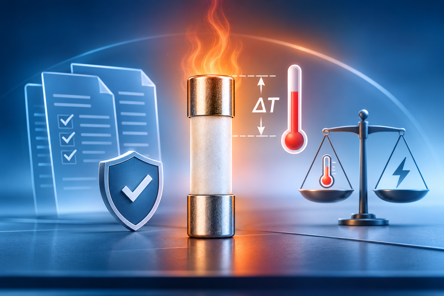
Fuse Temperature Rise Standards: Understanding UL 248-13, IEC 60269-4 and Safety Design Trade-Offs
Introduction
Fuse temperature rise is one of the most important parameters in electrical fuse design, particularly in high-current applications, semiconductor protection systems, photovoltaic installations, electric vehicles, and industrial power distribution networks. It directly affects electrical efficiency, component reliability, operating stability, and overall system safety.
When an electrical fuse carries current, its internal resistance generates heat. If this heat is not effectively managed, the fuse temperature can increase beyond acceptable operating limits, potentially damaging surrounding components, accelerating material degradation, and creating serious safety hazards.
To ensure reliable thermal performance, international standards establish specific testing requirements and temperature rise limits. Among the most important are UL 248-13 and IEC 60269-4, which address fuse performance and protection requirements in demanding electrical applications.
However, achieving the lowest possible temperature rise is not necessarily the ultimate goal of fuse engineering. Designers must carefully balance thermal performance, electrical resistance, fusing characteristics, and short-circuit interruption capabilities.
This article examines fuse temperature rise standards, the factors influencing thermal performance, and the critical engineering trade-offs involved in designing safe and reliable electrical fuses.
1. What Is Fuse Temperature Rise?
Fuse temperature rise refers to the difference between the temperature measured at a specific point on a fuse and the surrounding ambient temperature while the fuse is operating under defined electrical conditions.
It is generally expressed using the following formula:
Temperature Rise (ΔT) = Measured Fuse Temperature − Ambient Temperature
For example, if the ambient temperature is 25°C and the fuse terminal temperature reaches 85°C, the temperature rise is:
ΔT = 85°C − 25°C = 60K
Temperature differences expressed in Kelvin and degrees Celsius have the same numerical value.
Temperature rise is an important indicator of a fuse's thermal performance. A lower temperature rise generally indicates reduced heat generation or more effective heat dissipation.
Excessive temperature rise can lead to several problems:
-
Accelerated ageing of insulation and surrounding materials.
-
Increased electrical resistance in connected components.
-
Thermal stress on fuse terminals and contact surfaces.
-
Deterioration of electrical connections.
-
Reduced equipment service life.
-
Increased risk of overheating and electrical failure.
For this reason, temperature rise testing is an essential part of fuse design verification and quality control.
2. Understanding UL 248-13 and IEC 60269-4 Temperature Rise Requirements
International fuse standards provide technical requirements to ensure that electrical protection devices operate safely and consistently under specified conditions.
Two important standards in semiconductor fuse applications are UL 248-13 and IEC 60269-4.
2.1 UL 248-13: Semiconductor Fuse Requirements
UL 248-13 addresses supplemental requirements for semiconductor fuses. These fuses are designed to protect sensitive power electronic components against excessive currents and short-circuit conditions.
Semiconductor fuses are commonly used in:
-
Industrial power converters.
-
Variable-frequency drives.
-
Power semiconductor modules.
-
Battery energy storage systems.
-
Electric vehicle power electronics.
-
Renewable energy conversion equipment.
Temperature rise is an important consideration because semiconductor fuses frequently operate in compact electrical enclosures with limited cooling capacity.
Under the specific test conditions described in the referenced technical requirements, the temperature rise at the fuse's metal terminals must not exceed 130K after the fuse reaches thermal stability at its rated current for one hour.
This requirement helps evaluate whether the fuse can operate within an acceptable thermal range under defined conditions.
It is important to understand that the 130K figure is associated with a particular test point and test procedure. It should not be interpreted as a universal temperature limit for every fuse component or installation.
2.2 IEC 60269-4: International Requirements for Semiconductor Protection
IEC 60269-4 establishes requirements for fuse-links used to protect semiconductor devices.
Its scope includes important electrical and operational characteristics, including:
-
Rated current and rated voltage.
-
Breaking capacity.
-
Time-current characteristics.
-
Power dissipation.
-
Temperature rise.
-
Short-circuit protection performance.
The standard is particularly relevant to applications where semiconductor components require fast and dependable overcurrent protection.
Unlike conventional circuit protection applications, semiconductor protection often involves highly sensitive components that can be damaged by extremely short-duration fault currents.
Consequently, fuse designers must consider both thermal performance and interruption speed.
2.3 Why Compliance Matters
Compliance with applicable fuse standards helps demonstrate that a fuse has been evaluated against defined safety and performance requirements.
However, passing a temperature rise test alone does not establish complete fuse safety.
A properly evaluated fuse must also demonstrate appropriate:
-
Breaking capacity.
-
Short-circuit interruption performance.
-
Electrical endurance.
-
Insulation performance.
-
Mechanical integrity.
-
Time-current characteristics.
The most effective fuse design considers all these parameters together rather than treating temperature rise as an isolated performance indicator.
3. Five Major Factors Affecting Fuse Temperature Rise
Fuse temperature rise depends on several interconnected electrical, mechanical, and environmental factors.
Understanding these factors helps engineers optimise fuse performance without compromising protection capabilities.
3.1 Cold Resistance
Cold resistance is the electrical resistance of a fuse measured before significant self-heating occurs.
According to Joule's heating law, the power dissipated as heat can be expressed as:
P = I² × R
Where:
-
P = Power dissipation in watts.
-
I = Current flowing through the fuse in amperes.
-
R = Electrical resistance in ohms.
At a given current, lower resistance generally produces less heat.
For example, reducing the resistance of a fuse element can decrease its power dissipation and help reduce operating temperature.
However, resistance also influences the fuse's melting characteristics.
A lower-resistance design may require different element dimensions or material configurations to achieve the required melting and interruption characteristics.
Therefore, reducing cold resistance without evaluating the complete time-current characteristics can compromise the intended protection performance.
3.2 Heat Dissipation Design
Heat dissipation determines how effectively the generated thermal energy moves away from the fuse element and terminals.
Several design parameters influence heat transfer:
-
Fuse body material.
-
Internal structural configuration.
-
Terminal material.
-
Surface area.
-
Thermal conductivity.
-
Internal contact arrangement.
-
Mounting configuration.
Materials with suitable thermal conductivity can help transfer heat away from critical areas.
Increasing the effective heat dissipation area can also reduce local temperature concentrations.
Nevertheless, thermal optimisation must account for the entire fuse assembly. Improving heat transfer at one location may influence the temperature distribution elsewhere.
3.3 Operating Current and Current Stability
Operating current has a significant influence on fuse temperature rise.
Because heat generation is proportional to the square of current, even a relatively small increase in current can produce a considerable increase in power dissipation.
For example, increasing current by 20% results in approximately 44% more resistive heating if resistance remains constant.
This relationship demonstrates why accurate rated-current selection and appropriate application conditions are essential.
Engineers should also consider:
-
Continuous operating current.
-
Temporary overload conditions.
-
Current fluctuations.
-
Harmonic content.
-
Cyclic loading.
-
Ambient temperature variations.
A fuse designed for one operating profile may experience significantly different thermal behaviour in another application.
3.4 Copper Busbar Specifications and Connection Quality
The electrical connection between the fuse and the surrounding circuit is another important factor.
Copper busbars provide an electrical path for current, but their dimensions and installation conditions affect resistance and heat generation.
Important considerations include:
-
Busbar cross-sectional area.
-
Busbar length.
-
Copper conductivity.
-
Contact surface condition.
-
Terminal tightening torque.
-
Contact pressure.
-
Connection resistance.
A smaller busbar cross-section or longer conductor length can increase electrical resistance and generate additional heat.
Poor electrical contact can also create localised hot spots, even when the fuse itself performs correctly.
For this reason, temperature rise testing should consider the specified mounting arrangement and connection conditions.
3.5 Ambient Temperature and Environmental Conditions
Environmental conditions strongly influence the thermal behaviour of electrical fuses.
A fuse operating in a well-ventilated environment may dissipate heat more effectively than an identical fuse installed inside a compact, enclosed electrical cabinet.
Key environmental factors include:
-
Ambient temperature.
-
Airflow and ventilation.
-
Enclosure dimensions.
-
Nearby heat-generating components.
-
Installation orientation.
-
Thermal insulation.
-
Altitude and cooling conditions.
When designing electrical systems, engineers should evaluate the actual installation environment rather than relying exclusively on laboratory test results.
4. The Engineering Trade-Off Between Low Temperature Rise and Fast Fusing
One of the most important challenges in semiconductor fuse design is balancing low temperature rise with fast fault-current interruption.
At first glance, reducing resistance appears to be an obvious solution for improving thermal performance.
However, fuse operation involves a complex relationship between resistance, element geometry, thermal energy, melting behaviour, and arc interruption.
4.1 Why Lower Resistance Is Not Always Better
Reducing cold resistance generally decreases power dissipation under normal operating conditions.
However, changes in fuse element resistance and geometry can also affect the energy required to melt the element.
Depending on the design, a fuse with lower resistance may exhibit longer pre-arcing times or different short-circuit operating characteristics.
This can become problematic in semiconductor protection applications.
Sensitive power electronic components may be unable to withstand prolonged fault-current exposure.
Therefore, a fuse that demonstrates excellent temperature rise performance but interrupts fault currents too slowly may not provide adequate protection.
4.2 The Importance of Fast Short-Circuit Interruption
Semiconductor devices can be extremely vulnerable to short-circuit currents.
During a fault, excessive current can rapidly generate heat within semiconductor junctions and internal conductive structures.
If the protective fuse does not interrupt the fault quickly enough, the protected equipment may experience irreversible damage.
For demanding semiconductor protection applications, engineers may require interruption within milliseconds under specified fault conditions.
For example, a design target of less than 10 milliseconds may be relevant to certain high-current fault scenarios.
However, the actual required interruption time depends on the fuse characteristics, prospective fault current, circuit voltage, and withstand capability of the protected semiconductor.
The key performance parameters include:
-
Pre-arcing time.
-
Arcing time.
-
Total clearing time.
-
Peak let-through current.
-
Total clearing I²t.
-
Rated breaking capacity.
These parameters must be evaluated together to determine whether a fuse can provide effective protection.
4.3 Why Safety Must Take Priority Over Extremely Low Temperature Rise
A fuse is primarily a protective device.
Its most important responsibility is to interrupt dangerous overcurrents and short circuits safely and reliably.
Although low temperature rise improves thermal performance, it should never be achieved at the expense of reliable fault interruption.
A fuse that operates cooler under normal conditions but fails to interrupt a dangerous short circuit presents a serious safety risk.
Consequently, professional fuse engineering follows a balanced approach:
-
Establish the required protection and interruption characteristics.
-
Ensure reliable operation under specified fault conditions.
-
Optimise resistance and power dissipation.
-
Improve heat dissipation through appropriate structural and material choices.
-
Verify temperature rise against applicable standards.
-
Confirm performance through comprehensive testing.
This approach ensures that thermal optimisation supports the primary safety function of the fuse.
5. What Is an Appropriate Fuse Temperature Rise?
There is no single ideal temperature rise value suitable for every fuse application.
The acceptable value depends on the applicable standard, rated current, terminal configuration, mounting conditions, ambient temperature, and surrounding equipment requirements.
For certain semiconductor fuse applications, a terminal temperature rise below 130K is an important benchmark under the specified test conditions.
In practical engineering and product development, designers may also aim for lower temperature rise values, such as approximately 50K–70K, depending on the application and design requirements.
These lower figures should be understood as potential engineering targets rather than universal mandatory limits.
The objective is to achieve sufficient thermal margin while maintaining the required electrical protection characteristics.
An excessively aggressive temperature reduction target can create unnecessary design constraints if it negatively affects the fuse's interruption performance.
6. How to Conduct Reliable Fuse Temperature Rise Testing
Accurate temperature rise testing is essential for verifying fuse thermal performance.
A reliable test should follow the applicable standard and use controlled electrical and environmental conditions.
Step 1: Prepare the Test Sample
Select the fuse sample according to the rated current, voltage, and intended application.
Check the following before testing:
-
Fuse dimensions.
-
Terminal condition.
-
Contact surfaces.
-
Electrical resistance.
-
Mounting configuration.
-
Rated electrical parameters.
The sample should be installed using the prescribed connection arrangement.
Step 2: Establish Ambient Conditions
Record the ambient temperature before applying current.
The testing environment should provide stable and controlled conditions to minimise measurement uncertainty.
Airflow, surrounding equipment, and mounting arrangements should also be documented.
Step 3: Apply Rated Current
Operate the fuse at its specified rated current under the relevant standard's test conditions.
The current should remain sufficiently stable throughout the test.
Any unexpected current variation can influence the measured temperature rise.
Step 4: Monitor Temperature
Measure the temperature at the designated locations, particularly the fuse terminals and other specified measurement points.
Suitable measurement techniques may include:
-
Calibrated thermocouples.
-
Precision temperature measurement instruments.
-
Infrared thermal analysis.
-
Automated temperature monitoring systems.
The measurement method should be appropriate for the test requirements and should not significantly disturb the thermal conditions.
Step 5: Confirm Thermal Stability
Allow the fuse to operate until thermal stability is achieved.
For the specific one-hour rated-current test condition described in the UL 248-13 reference, the temperature rise requirement applies after the prescribed stabilisation period.
The applicable standard should always determine the exact test duration and acceptance criteria.
Step 6: Calculate Temperature Rise
Calculate temperature rise using the difference between the measured fuse temperature and ambient temperature.
For example:
-
Ambient temperature: 25°C.
-
Fuse terminal temperature: 80°C.
-
Temperature rise: 55K.
Compare the measured result with the relevant acceptance criteria.
Step 7: Analyse and Document Results
Record the following information:
-
Rated current.
-
Test voltage, where applicable.
-
Ambient temperature.
-
Terminal temperatures.
-
Temperature rise.
-
Measurement locations.
-
Test duration.
-
Mounting configuration.
-
Test equipment and calibration details.
Complete documentation supports repeatability, traceability, and engineering verification.
7. Common Mistakes in Fuse Temperature Rise Evaluation
Even when testing equipment is accurate, incorrect test arrangements or incomplete analysis can produce misleading results.
Several common mistakes should be avoided.
Focusing Only on the Fuse Body
Temperature measurements should include the relevant terminals and other locations required by the applicable test procedure. The hottest or most important measurement point may not be on the fuse body.
Ignoring Connection Resistance
Poor terminal contact or inappropriate busbar dimensions can create additional heat and distort the evaluation of fuse performance.
Comparing Results from Different Test Conditions
Temperature rise results are meaningful only when the test conditions are sufficiently comparable.
Differences in ambient temperature, mounting arrangements, airflow, and current can lead to significantly different measurements.
Prioritising Low Temperature Over Protection Performance
A low temperature rise does not automatically indicate superior fuse safety. Short-circuit interruption capability and energy limitation must also be evaluated.
Ignoring Real Installation Conditions
A fuse that performs well under laboratory conditions may experience higher temperatures in an enclosed electrical cabinet with limited ventilation.
Engineers should therefore consider both standardised testing and the intended operating environment.
8. Designing a High-Performance Fuse: A Balanced Engineering Approach
Developing a high-performance fuse requires an integrated approach to electrical, thermal, and mechanical design.
Rather than optimising one parameter independently, engineers must consider the complete operating behaviour of the protective device.
A successful design should achieve the following objectives:
Reliable Overcurrent Protection
The fuse must operate according to its intended time-current characteristics and provide dependable protection against overloads and short circuits.
Controlled Temperature Rise
Power dissipation and heat generation should remain within acceptable limits under specified operating conditions.
Appropriate Breaking Capacity
The fuse must safely interrupt the prospective fault current at its rated voltage and under the conditions specified by the applicable requirements.
Optimised Electrical Resistance
Fuse resistance should be controlled to balance normal operating losses with the required fusing characteristics.
Effective Thermal Management
Suitable materials, terminal structures, and heat dissipation arrangements should minimise excessive temperature concentrations.
Consistent Manufacturing Quality
Manufacturing tolerances, material consistency, contact quality, and inspection procedures all influence the final electrical and thermal performance of a fuse.
These factors collectively determine whether a fuse can deliver reliable protection throughout its intended service life.
9. Conclusion: Safety, Thermal Performance and Compliance Must Work Together
Fuse temperature rise is a critical parameter in electrical protection engineering, particularly in semiconductor applications where both thermal stability and rapid fault interruption are essential.
UL 248-13 and IEC 60269-4 provide important frameworks for evaluating fuse performance and ensuring that protective devices meet relevant technical requirements.
However, achieving the lowest possible temperature rise should not become the only design objective.
Lower electrical resistance can reduce normal operating losses, but changes in resistance and fuse element geometry may also influence melting characteristics and interruption behaviour.
For this reason, effective fuse design requires a careful balance between temperature rise, electrical resistance, heat dissipation, breaking capacity, and short-circuit protection.
The most reliable fuse is not necessarily the one that operates at the lowest temperature. It is the one that maintains controlled thermal performance while providing fast, dependable, and safe interruption under specified fault conditions.
Ultimately, comprehensive testing, accurate engineering calculations, and compliance with applicable international standards are essential to developing safe and reliable electrical protection solutions.
Frequently Asked Questions (FAQs)
1. What is the temperature rise limit for semiconductor fuses under UL 248-13?
Under the specific test conditions described in the technical reference, the temperature rise at the fuse's metal terminals must not exceed 130K after stabilisation at rated current for one hour. The applicable edition and detailed test procedure should be consulted for formal compliance evaluation.
2. What is the difference between UL 248-13 and IEC 60269-4?
Both standards address semiconductor fuse requirements, including important electrical and thermal performance characteristics. UL 248-13 is associated with North American requirements, while IEC 60269-4 provides an international framework for semiconductor fuse-links.
3. Why is fuse temperature rise important?
Excessive temperature rise can accelerate material ageing, damage electrical connections, reduce equipment reliability, and increase overheating risks. Temperature rise testing helps verify thermal performance under defined operating conditions.
4. Does lower fuse resistance always mean better performance?
No. Lower resistance generally reduces power dissipation, but changes in fuse element resistance and geometry can affect melting and interruption characteristics. Designers must evaluate thermal performance and protection capability together.
5. What causes excessive fuse temperature rise?
Common causes include high operating current, excessive internal resistance, poor electrical connections, undersized busbars, inadequate heat dissipation, elevated ambient temperatures, and insufficient ventilation.
6. How is fuse temperature rise calculated?
Temperature rise is calculated by subtracting ambient temperature from the measured fuse temperature.
Temperature Rise (ΔT) = Fuse Temperature − Ambient Temperature.
For example, a terminal temperature of 90°C at an ambient temperature of 30°C produces a temperature rise of 60K.
7. Why is fast fusing important for semiconductor protection?
Semiconductor devices can be damaged by high fault currents within very short periods. A properly selected semiconductor fuse helps limit the energy passing through the circuit and interrupts dangerous fault currents before they cause unacceptable damage.
8. Is a temperature rise of 50K–70K always required?
No. A temperature rise of 50K–70K may represent a practical design target in certain applications, but it is not a universal requirement. The applicable standard, fuse construction, installation conditions, and equipment specifications determine the appropriate acceptance criteria.
9. What factors should engineers consider when selecting a semiconductor fuse?
Important selection parameters include rated current, rated voltage, breaking capacity, time-current characteristics, total clearing I²t, power dissipation, temperature rise, installation conditions, and compatibility with the protected semiconductor device.
10. Can a fuse pass temperature rise testing but still be unsafe?
Yes. Temperature rise testing evaluates thermal performance under defined conditions. A fuse must also satisfy relevant requirements for short-circuit interruption, breaking capacity, electrical endurance, and other applicable safety characteristics.