Electrical Fuses Blog
Eaton Bussmann Series Electrical Fuses – Blog & Fachwissen
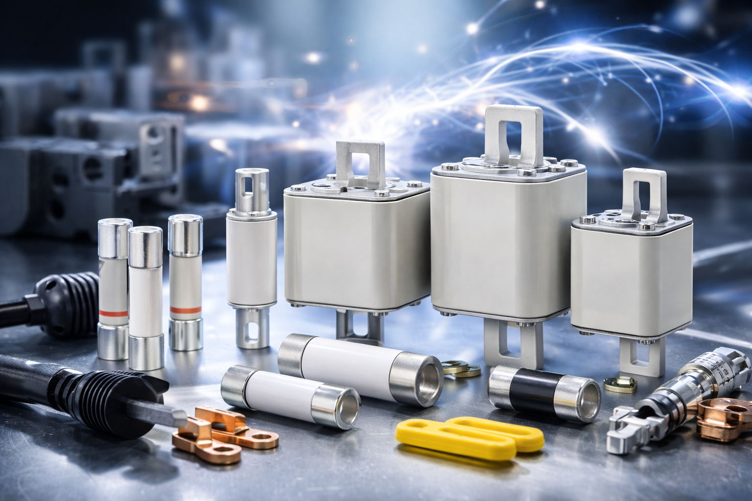
Im Eaton Bussmann Series Electrical Fuses Blog finden Sie fundiertes Fachwissen rund um elektrische Sicherungen, Überstromschutz und moderne Schutzkonzepte für industrielle und gewerbliche Anwendungen. Diese Kategorie bündelt alle Blogartikel, technischen Beiträge und Praxisguides zu den Sicherungssystemen und Serien von Eaton Bussmann.
Eaton Bussmann zählt weltweit zu den führenden Herstellern von elektrischen Sicherungen, und ihre Serien stehen für Sicherheit, Normkonformität und höchste Zuverlässigkeit in anspruchsvollen elektrischen Systemen.
Was Sie im Eaton Bussmann Sicherungen Blog erwartet
Unsere Blogbeiträge helfen Ingenieuren, Einkäufern, Technikern und Planern dabei, die richtige Sicherungslösung zu finden und technische Zusammenhänge besser zu verstehen.
Themenschwerpunkte dieser Kategorie:
-
🔌 Überblick über Eaton Bussmann Sicherungsserien
-
⚙️ Unterschiede zwischen UL-, IEC- und Spezial-Sicherungen
-
📘 Technische Erklärungen zu Kennlinien, Auslöseverhalten & Bemessungswerten
-
🏭 Anwendungstipps für Industrie, Maschinenbau & Energieverteilung
-
🚗 Beiträge zu EV-, DC- und Hochvolt-Sicherungen
-
🛠 Best Practices für Auswahl, Installation und Wartung
Alle Inhalte sind praxisnah, verständlich aufbereitet und technisch fundiert.
Eaton Bussmann Sicherungsserien im Fokus
Der Blog behandelt regelmäßig verschiedene Eaton Bussmann Series Electrical Fuses, darunter:
-
Industrial Fuses
-
North American (UL) Fuse Series
-
IEC Sicherungsserien
-
High Speed & Semiconductor Fuses
-
EV & DC Sicherungen
-
Supplementary & Specialty Fuses
So erhalten Sie einen umfassenden Überblick über das Eaton Bussmann Portfolio und dessen Einsatzmöglichkeiten.
Fachwissen für sichere elektrische Systeme
Elektrische Sicherungen sind ein zentraler Bestandteil jeder sicheren Stromversorgung. Der Eaton Bussmann Series Electrical Fuses Blog unterstützt Sie dabei, Risiken zu minimieren, Normen einzuhalten und die Lebensdauer Ihrer Anlagen zu verlängern.
Ganz gleich, ob Sie Grundlagenwissen suchen oder tief in spezielle Sicherungsserien eintauchen möchten – hier finden Sie relevante, aktuelle und suchmaschinenoptimierte Inhalte rund um Eaton Bussmann Electrical Fuses.
👉 Jetzt Blogartikel entdecken und Ihr Wissen über Eaton Bussmann Sicherungsserien gezielt erweitern.
- Details
- Category: Electrical Fuses Blog
 eaton-bussmann-series-photovoltaic-fuses-catalogue-ca135004en.pdf  | [Eaton Bussmann PV Fuses] | 0 kB |
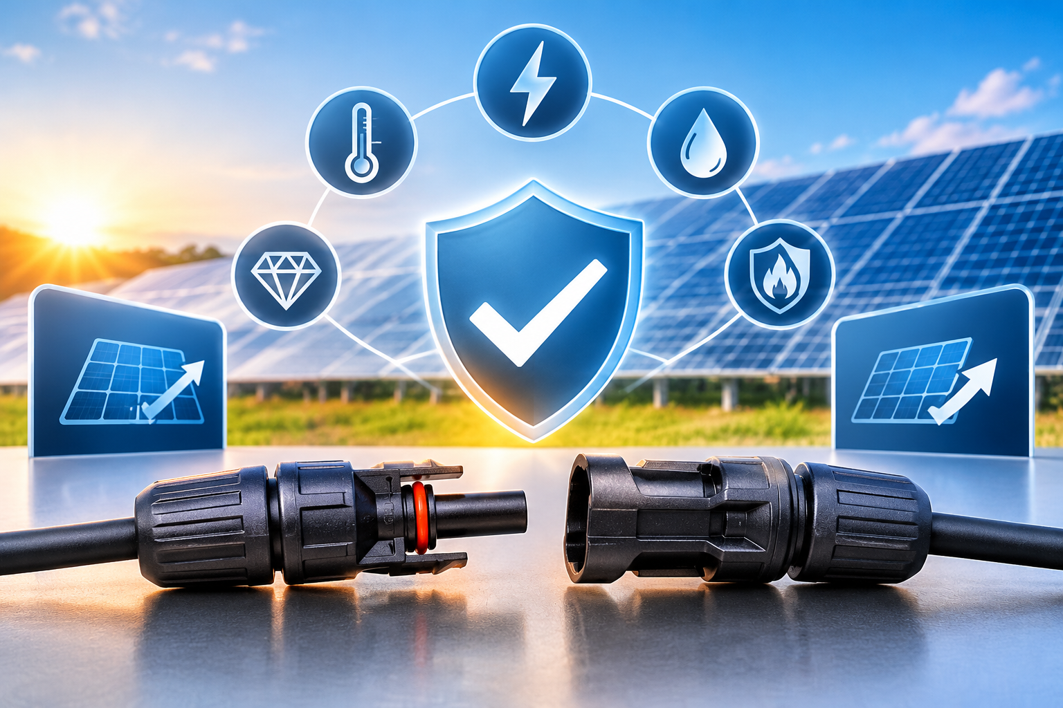
How to Choose the Right Solar Connector for 1000V and 1500V PV Systems
Introduction
As solar photovoltaic (PV) technology continues to advance, modern solar installations are increasingly adopting higher system voltages to improve energy efficiency, reduce installation costs, and optimize overall performance. Among the most common configurations are 1000V and 1500V DC solar systems, both widely used in residential, commercial, industrial, and utility-scale solar projects.
While selecting solar panels, inverters, and cables is essential, choosing the right solar connector is equally important. Solar connectors provide secure electrical connections between PV modules, cables, and other system components. They must withstand high DC voltages, varying environmental conditions, and long-term operational demands.
Choosing an unsuitable connector can lead to overheating, electrical failures, power losses, insulation breakdown, and potential fire hazards.
So, how do you choose the right solar connector for a 1000V or 1500V PV system?
This guide explains the key technical specifications, safety requirements, material considerations, and installation factors to help you make an informed decision.
1. Understand the Difference Between 1000V and 1500V Solar Systems
Before selecting a solar connector, it is important to understand the operating voltage of your PV system.
1000V Solar Systems
A 1000V DC solar system is commonly used in commercial and industrial solar installations. It offers a practical balance between system efficiency, component compatibility, and installation requirements.
These systems typically feature:
-
Lower maximum DC voltage compared with 1500V configurations.
-
Established compatibility with a wide range of PV components.
-
Suitable performance for commercial and medium-sized solar projects.
-
Well-established installation and maintenance practices.
1500V Solar Systems
A 1500V DC solar system allows more solar modules to be connected in series within a single string, subject to the system's design limits.
This configuration offers several advantages:
-
Fewer parallel strings may be required.
-
Reduced cable requirements in suitable system designs.
-
Potentially lower balance-of-system costs.
-
Improved efficiency for large-scale solar power plants.
However, higher voltage increases the demands placed on insulation, electrical clearance, connector construction, and protection against arcing.
Important: A connector rated for 1000V DC should never be assumed suitable for a 1500V system. Always verify that its specified voltage rating meets or exceeds the maximum calculated system voltage.
2. Check the Rated DC Voltage
Rated voltage is one of the most important specifications when choosing a solar connector.
For a 1000V PV system, select a connector specifically certified and rated for the required 1000V DC operating conditions. For a 1500V PV system, choose a connector with an appropriate 1500V DC rating.
The actual maximum string voltage must also be calculated using the solar module's open-circuit voltage (Voc), the number of modules connected in series, and the temperature correction factor.
Cold weather can increase the open-circuit voltage of solar modules. Therefore, the maximum system voltage should be calculated using the lowest expected ambient temperature rather than standard testing conditions alone.
Consider the following factors:
-
Maximum PV system voltage.
-
Module open-circuit voltage.
-
Number of modules connected in series.
-
Minimum expected operating temperature.
-
Connector insulation and dielectric performance.
Selecting a connector based only on the nominal system voltage without considering cold-temperature conditions can create serious safety risks.
3. Evaluate Current Carrying Capacity
Voltage is not the only specification that matters. The connector must also support the maximum expected operating current of the PV system.
Solar connectors are designed with specific rated current limits. Exceeding these limits can cause excessive resistance, overheating, insulation deterioration, and premature connector failure.
When evaluating current capacity, consider:
Module short-circuit current: The connector must be suitable for the maximum current associated with the connected PV modules.
Current correction factors: Applicable design standards may require current adjustments based on operating conditions and circuit configuration.
Temperature rise: High ambient temperatures can affect the connector's ability to carry current safely.
Contact resistance: Low and stable contact resistance helps minimize energy losses and heat generation.
For reliable performance, select connectors whose rated current is appropriate for the maximum design current, including applicable safety factors and derating requirements.
4. Choose High-Quality Insulation Materials
Insulation plays a critical role in protecting solar connectors against electrical leakage, short circuits, and insulation breakdown.
This becomes particularly important in 1500V PV systems, where connectors must withstand higher electrical stress.
Common insulation material considerations include:
-
UV resistance: Solar connectors are continuously exposed to sunlight, making ultraviolet resistance essential.
-
Temperature resistance: Materials should maintain their electrical and mechanical properties under high operating temperatures.
-
Weather resistance: Connectors must withstand rain, humidity, dust, and changing environmental conditions.
-
Flame resistance: Suitable flame-retardant properties help improve electrical safety.
-
Insulation stability: Materials should resist cracking, deformation, and deterioration throughout the intended service life.
High-quality insulation materials contribute to long-term connector reliability and help reduce the risk of electrical faults.
5. Consider Contact Materials and Electrical Conductivity
The conductive contacts inside a solar connector directly influence its electrical performance.
Poor-quality contacts or unsuitable conductive materials can increase contact resistance, resulting in heat generation and power losses.
When evaluating contact materials, consider the following characteristics:
Electrical conductivity: High conductivity helps reduce resistance and minimize energy losses.
Corrosion resistance: Solar connectors may operate in humid, coastal, or industrial environments. Corrosion-resistant contact materials help maintain stable electrical connections.
Mechanical strength: Contacts should retain their shape and pressure during repeated thermal expansion and contraction.
Contact stability: Secure contact engagement helps prevent loose connections and overheating.
The quality of the internal contact structure is just as important as the external connector housing.
6. Check IP Protection and Environmental Resistance
Solar PV connectors are frequently installed outdoors and exposed to demanding environmental conditions.
An appropriate ingress protection (IP) rating helps prevent dust and water from entering the connector assembly.
When selecting a connector, evaluate:
-
Protection against dust penetration.
-
Resistance to water exposure.
-
Performance under heavy rain and humidity.
-
Resistance to UV radiation.
-
Suitability for high and low temperatures.
-
Protection against environmental contamination.
An IP rating should be evaluated according to the applicable testing standard and the connector's specified mating and installation conditions.
It is also important to understand that an IP rating does not automatically guarantee suitability for every outdoor installation. Correct assembly, proper mating, and compliance with installation instructions remain essential.
7. Ensure Mechanical Compatibility and Secure Connections
A solar connector must provide a reliable mechanical connection as well as effective electrical performance.
Poorly matched connectors can result in loose connections, increased contact resistance, overheating, and electrical arcing.
Before selecting a connector, verify:
-
Compatibility with the specified PV cable size.
-
Correct conductor cross-section.
-
Suitable crimping requirements.
-
Secure locking mechanisms.
-
Proper sealing components.
-
Mechanical strength and connection stability.
Avoid connecting products from different manufacturers or product families unless their compatibility has been explicitly verified and approved.
Connectors that appear physically similar are not necessarily electrically or mechanically interchangeable.
Using compatible connector components and approved assembly tools helps ensure a secure, reliable connection.
8. Verify Compliance With International Standards and Certifications
Certification is an essential consideration when purchasing solar connectors for 1000V and 1500V PV systems.
Relevant standards and certification requirements help demonstrate that a connector has undergone appropriate testing for electrical safety, mechanical performance, and environmental durability.
Depending on the application and market, check for:
-
IEC 62852 compliance for connectors used in photovoltaic DC applications.
-
Applicable national and regional electrical safety requirements.
-
Verified voltage and current ratings.
-
Insulation and dielectric test results.
-
Temperature cycling performance.
-
Environmental and mechanical testing.
-
Traceable product certification and technical documentation.
Do not rely solely on a manufacturer's stated specifications. Request relevant certificates, test reports, and technical datasheets before purchasing.
Certification should apply to the exact connector model and configuration being installed.
9. Consider Installation Conditions and Long-Term Maintenance
Even a technically suitable solar connector can fail if it is incorrectly installed.
Installation quality has a direct impact on electrical safety, system efficiency, and service life.
Follow these best practices:
-
Use connectors compatible with the selected PV cables and system voltage.
-
Follow the specified cable stripping and crimping procedures.
-
Use the recommended crimping tools and dies.
-
Ensure contacts are correctly positioned and fully inserted.
-
Confirm that locking mechanisms are properly engaged.
-
Keep connector mating surfaces clean and free from contamination.
-
Avoid excessive cable tension and mechanical stress.
-
Follow manufacturer instructions for sealing and environmental protection.
-
Inspect connections during commissioning and scheduled maintenance.
Never disconnect a connector under load unless the equipment is specifically designed and rated for that operation. Follow appropriate isolation procedures and electrical safety requirements.
Regular inspection can help identify signs of overheating, discoloration, cracking, corrosion, or mechanical damage before they develop into serious failures.
10. Common Mistakes to Avoid When Choosing Solar Connectors
Several mistakes can compromise the safety and reliability of a PV installation.
Using 1000V connectors in 1500V systems
A lower-voltage connector cannot automatically be used in a higher-voltage application. Always check the certified voltage rating.
Ignoring current ratings
A connector with insufficient current capacity may overheat during normal operation or under demanding environmental conditions.
Choosing products based only on price
Low initial purchasing costs may lead to higher maintenance expenses, premature replacement, and potential system downtime.
Mixing incompatible connector components
Physically similar connectors are not necessarily compatible. Use approved mating components.
Overlooking environmental conditions
UV exposure, moisture, temperature fluctuations, and dust can affect connector performance over time.
Ignoring installation quality
Incorrect crimping, incomplete insertion, and loose connections can increase electrical resistance and create dangerous hot spots.
Avoiding these mistakes helps improve the reliability and operational safety of solar installations.
11. 1000V vs. 1500V Solar Connector Selection: Key Differences
Although both system configurations require high-quality photovoltaic connectors, their electrical requirements differ.
| Selection Factor | 1000V PV System | 1500V PV System |
|---|---|---|
| Rated voltage | Suitable 1000V DC rating | Suitable 1500V DC rating |
| Insulation performance | Appropriate for 1000V application | Verified for higher voltage stress |
| Current capacity | Based on system design current | Based on system design current |
| Contact quality | Low and stable contact resistance | Low and stable contact resistance |
| Environmental protection | Suitable for outdoor installation | Suitable for outdoor installation |
| Certification | Applicable PV connector standards | Applicable PV connector standards |
| Installation | Approved mating and crimping procedures | Approved mating and crimping procedures |
The most important distinction is the connector's verified voltage rating and insulation performance. Current capacity, environmental resistance, mechanical compatibility, and certification must also be assessed for both configurations.
12. Final Checklist for Selecting the Right Solar Connector
Before purchasing connectors for a 1000V or 1500V PV installation, review the following checklist:
-
The rated DC voltage meets the maximum calculated system voltage.
-
The current rating meets the maximum design current.
-
Insulation materials provide suitable electrical protection.
-
Contact materials offer reliable conductivity and corrosion resistance.
-
The IP rating matches the installation environment.
-
The connector is compatible with the selected PV cable.
-
Mating components are approved for use together.
-
The product meets applicable photovoltaic connector standards.
-
Certification and technical documentation are available.
-
Installation tools and procedures are clearly specified.
A systematic evaluation of these factors helps reduce installation risks and supports long-term PV system performance.
Conclusion
Choosing the right solar connector for 1000V and 1500V PV systems is an important part of designing a safe, efficient, and reliable solar installation.
The selection process should go beyond basic voltage ratings. Current carrying capacity, insulation quality, contact materials, environmental protection, mechanical compatibility, certification, and installation requirements all influence connector performance.
For 1000V systems, select connectors that meet the calculated maximum voltage and current requirements. For 1500V systems, ensure the connectors are specifically rated and tested for the higher voltage application.
Ultimately, the right solar connector is one that meets the electrical and environmental requirements of the installation, complies with relevant standards, and provides dependable performance throughout the system's intended service life.
Taking the time to evaluate these technical factors can help prevent electrical failures, minimize maintenance costs, and improve the long-term reliability of photovoltaic power systems.
- Details
- Category: Electrical Fuses Blog
| eaton-bussmann-series-dc-fuses-catalog-ca135009en-us.pdf | [Eaton Bussmann DC Fuses] | 0 kB |
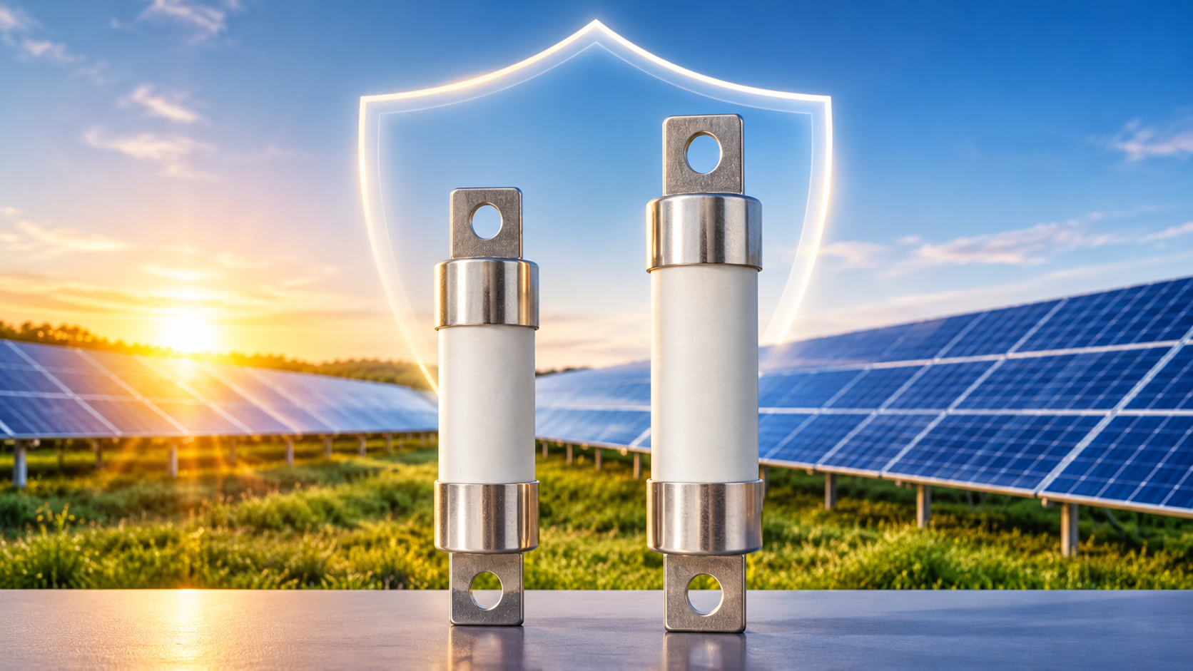
Where Are DC Fuses Used in Solar PV Systems?
Introduction
Solar photovoltaic (PV) systems generate electricity through direct current (DC), which must be safely managed and protected before it reaches the inverter. One of the most important components used for this purpose is the DC fuse.
DC fuses in solar PV systems help protect electrical circuits, cables and solar modules from overcurrent conditions, including reverse current caused by faults in parallel-connected PV strings. By interrupting excessive current, they reduce the risk of equipment damage, overheating and electrical hazards.
However, DC fuses are not installed in exactly the same locations in every solar installation. Their placement depends on the system configuration, number of parallel strings, electrical ratings and applicable installation requirements.
So, where are DC fuses used in solar PV systems? Let's explore their main installation locations, functions and selection considerations.
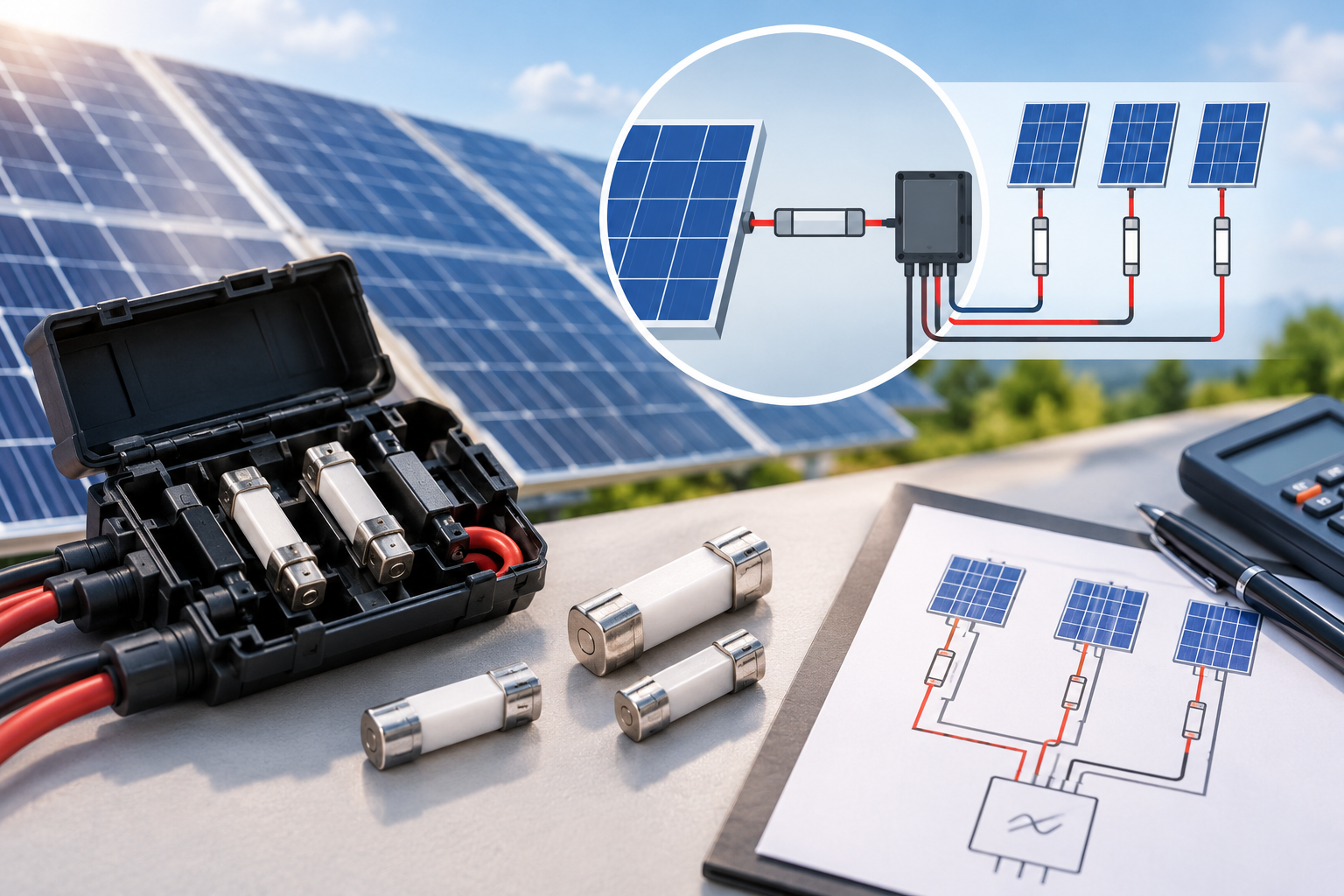
1. PV String Circuits and Combiner Boxes
One of the most common applications of DC fuses in solar PV systems is string-level circuit protection.
A solar PV array typically consists of multiple solar panels connected in series to form individual strings. Several strings may then be connected in parallel to increase the system's total power output.
When multiple strings operate in parallel, a fault in one string can allow current from the healthy strings to flow backwards into the faulty circuit. This reverse current may exceed the permitted limits of the solar modules and connecting cables.
String fuses help prevent this situation by disconnecting the affected circuit when the current exceeds the fuse's operating limits.
How Do String Fuses Work?
In a typical PV combiner box, each incoming solar string may be connected through an individual fuse link and fuse holder before reaching the common DC busbar.
For example, consider a solar installation with six parallel PV strings. If one string develops a fault, the remaining five strings may contribute reverse current towards the faulty string.
The fuse installed in the affected string is designed to interrupt this excessive current when necessary, helping protect the modules and associated wiring.
Depending on the system design and applicable electrical requirements, string fuses may be installed in one or both DC poles. They can also be integrated into other DC protection equipment.
2. Solar Array and Sub-Array Output Circuits
Another important application of DC fuses is at the output of solar array sections and sub-arrays.
When multiple PV strings are combined, their output current increases. The combined circuit therefore requires appropriate protection based on its current-carrying capacity and the electrical characteristics of the connected equipment.
In some installations, larger DC fuse links are installed at the combiner box output or sub-array output.
These fuses can provide protection for outgoing conductors and help coordinate the protection system with downstream DC equipment.
Why Are Output Fuses Important?
Array output fuses can serve several purposes:
-
Protect outgoing DC cables against excessive current.
-
Help isolate faulty sections of a PV array.
-
Reduce the risk of conductor overheating.
-
Support coordination between upstream and downstream protection devices.
-
Improve the overall safety and reliability of the solar installation.
However, an output fuse is not automatically required in every combiner box. Its necessity depends on the available current sources, cable ratings, system configuration and downstream equipment requirements.
3. Near the Inverter DC Input
DC fuses may also be installed near the DC input of a solar inverter.
The inverter is responsible for converting the DC electricity generated by solar panels into alternating current (AC) for use in electrical installations or connection to the power grid.
Before reaching the inverter, DC power may pass through a combiner box and other protective devices.
Depending on the system architecture, a fuse or fused switching device may be installed between the combiner box and the inverter.
What Is the Purpose of an Inverter-Side DC Fuse?
An inverter-side fuse helps protect the relevant incoming DC circuit against excessive current.
It is important to understand that this fuse does not automatically protect every internal component of the inverter. Internal inverter protection is determined by the equipment's design and manufacturer specifications.
Some modern inverters also include integrated string fuses in their DC input sections, reducing the need for separate external string protection equipment.
Therefore, the installation design should always consider the inverter's built-in protection features and electrical requirements.
4. Do All Solar PV Strings Need DC Fuses?
No. Not every solar PV string requires an individual fuse.
The need for string-level overcurrent protection depends on the number of parallel strings and the amount of potential reverse current under fault conditions.
For example:
-
Single-string systems: Generally do not have other parallel strings capable of feeding reverse current into a faulty string.
-
Two-string systems: Depending on the module specifications and possible fault current, additional string fusing may not be necessary.
-
Multiple-string systems: As the number of parallel strings increases, the potential reverse current also increases, making string fuses more likely to be necessary.
Before deciding whether DC fuses are required, installers and system designers should evaluate several factors:
-
Maximum possible reverse current.
-
Solar module maximum series fuse rating.
-
DC cable current-carrying capacity.
-
Number of parallel-connected PV strings.
-
Inverter and combiner box specifications.
-
Applicable electrical standards and local installation requirements.
Correctly evaluating these parameters helps determine the appropriate protection arrangement for the PV system.
5. How to Select the Right DC Fuse for a Solar PV System
Choosing a suitable DC fuse involves more than matching its rated voltage and current to the solar installation.
A fuse must be compatible with the system's electrical characteristics, installation environment and intended protection function.
Here are the key factors to consider.
5.1 Maximum System Voltage
The fuse must have a DC voltage rating equal to or higher than the maximum possible system voltage.
Solar PV systems can operate at different voltage levels, commonly including 1000V DC and 1500V DC configurations.
The maximum voltage calculation should account for the open-circuit voltage (Voc) of the modules and the expected temperature conditions, rather than relying only on nominal operating voltage.
5.2 Rated Current
The fuse's rated current must be selected according to the circuit's expected operating current and applicable PV protection requirements.
The selection should consider module short-circuit current (Isc), the number of parallel strings, conductor ratings and the maximum series fuse rating specified by the module manufacturer.
An incorrectly rated fuse may cause unnecessary interruptions or fail to provide the required protection.
5.3 Breaking Capacity
Breaking capacity refers to the maximum fault current that a fuse can safely interrupt at its specified voltage.
Because PV installations can experience substantial fault currents, the fuse must have an adequate DC breaking capacity for the application.
5.4 Operating Temperature
Solar PV equipment is frequently installed in outdoor environments where temperatures can become high.
Ambient temperature, enclosure conditions, ventilation and heat dissipation can influence fuse performance.
These factors should be considered when selecting both the fuse link and its compatible fuse holder.
5.5 Fuse Holder Compatibility
The fuse holder is just as important as the fuse itself.
Its voltage rating, current capacity, terminal design and thermal performance must match the selected fuse and installation conditions.
Using an unsuitable fuse holder can create additional resistance, excessive heat and potential reliability problems.
6. What Is a gPV Fuse and Why Is It Used in Solar Systems?
A gPV fuse is a specialised full-range fuse link designed for photovoltaic applications.
The gPV classification is defined under IEC 60269-6, which covers fuse links for solar PV systems.
These fuses are designed to provide overcurrent protection in PV string and array circuits within their specified electrical ratings.
Compared with general-purpose fuse links, photovoltaic fuses are specifically intended to address the operating characteristics and protection requirements of solar DC circuits.
When selecting a gPV fuse, it is important to verify:
-
Rated DC voltage.
-
Rated current.
-
DC breaking capacity.
-
Fuse size and physical dimensions.
-
Compatibility with the fuse holder.
-
Compliance with relevant standards.
The gPV marking alone does not guarantee suitability. All electrical ratings must match the intended application.
7. Can AC Fuses Be Used in Solar PV DC Circuits?
No, an AC voltage rating alone is not sufficient to establish that a fuse is suitable for a DC application.
Although AC and DC fuses may look similar, interrupting DC fault current presents different technical challenges.
In AC circuits, current naturally passes through zero during each cycle, helping extinguish the electrical arc when a fuse operates.
In DC circuits, current does not have the same natural zero-crossing behaviour. Consequently, interrupting a DC fault can be more challenging.
A fuse used in a solar PV circuit must therefore have:
-
An appropriate DC voltage rating.
-
Sufficient DC breaking capacity.
-
A suitable current rating.
-
The correct application classification.
-
Compatibility with the installation requirements.
Using a fuse without an appropriate DC rating can compromise the safety and reliability of the entire PV protection system.
8. Common Mistakes to Avoid When Installing DC Fuses in Solar PV Systems
Correct fuse selection and installation are essential for reliable solar PV operation. Some common mistakes include:
1. Selecting a fuse based only on rated current
Voltage, breaking capacity, module specifications and installation conditions must also be considered.
2. Ignoring reverse current
Failing to calculate potential reverse current in parallel-connected strings can result in inadequate circuit protection.
3. Using an AC-rated fuse in a DC application
A suitable DC voltage rating and breaking capacity are essential for safe fault interruption.
4. Ignoring fuse holder specifications
An incompatible fuse holder may lead to poor electrical contact and excessive heat generation.
5. Overlooking operating temperature
High ambient temperatures and limited enclosure ventilation can affect fuse performance.
6. Installing unnecessary fuses
Adding fuses without evaluating the actual circuit configuration can increase system complexity and maintenance requirements.
Following the equipment manufacturer's instructions and applicable electrical standards helps avoid these problems.
Conclusion
DC fuses play an important role in protecting solar photovoltaic systems against excessive current and electrical faults. Their most common installation locations include PV string circuits, combiner boxes, array output circuits and, where required, inverter DC input connections.
However, not every solar installation requires fuses in all these locations. The correct protection arrangement depends on the number of parallel strings, potential reverse current, module specifications, cable capacity and inverter design.
Selecting the right DC fuse requires careful consideration of voltage rating, current rating, breaking capacity, operating temperature and fuse holder compatibility.
With appropriate fuse selection and installation, solar PV system designers can improve electrical safety, protect valuable equipment and support reliable long-term system operation.
Frequently Asked Questions (FAQs)
1. Where are DC fuses installed in solar PV systems?
DC fuses are commonly installed in PV string circuits, combiner boxes and array or sub-array output circuits. They may also be installed near the inverter's DC input, depending on the system design.
2. What is the main function of a DC fuse in a solar system?
The main function of a DC fuse is to interrupt excessive current caused by electrical faults. It helps protect solar modules, DC cables and connected equipment against damage.
3. Are DC fuses necessary for every solar panel?
No. Individual panel-level fuses are not universally required. Fuse requirements depend on the number of parallel-connected strings, potential reverse current, module specifications and applicable installation standards.
4. What is a PV combiner box fuse?
A PV combiner box fuse is a protective device installed in an incoming solar string circuit or, where required, at the combined output. It helps isolate faulty circuits and protect connected conductors.
5. What does gPV mean on a solar fuse?
gPV identifies a full-range fuse link designed specifically for photovoltaic applications under IEC 60269-6. It is used for overcurrent protection in solar PV string and array circuits.
6. What voltage rating should a solar DC fuse have?
The fuse's rated DC voltage must be equal to or greater than the maximum possible system voltage. Common solar PV system voltage classes include 1000V DC and 1500V DC.
7. Can a normal DC fuse be used in a solar PV system?
Not necessarily. The fuse must have suitable voltage, current and breaking-capacity ratings, along with an appropriate application classification. A photovoltaic-rated fuse is generally selected for PV string and array protection.
8. Why is breaking capacity important for solar DC fuses?
Breaking capacity determines the maximum fault current a fuse can safely interrupt at its specified voltage. An insufficient breaking capacity can compromise the safe interruption of a DC fault.
- Details
- Category: Electrical Fuses Blog
| eaton-bussmann-series-photovoltaic-fuses-catalogue-ca135004en.pdf | [Eaton Bussmann PV Fuses] | 0 kB |
Do PV Systems Always Require Fuses for Every String?
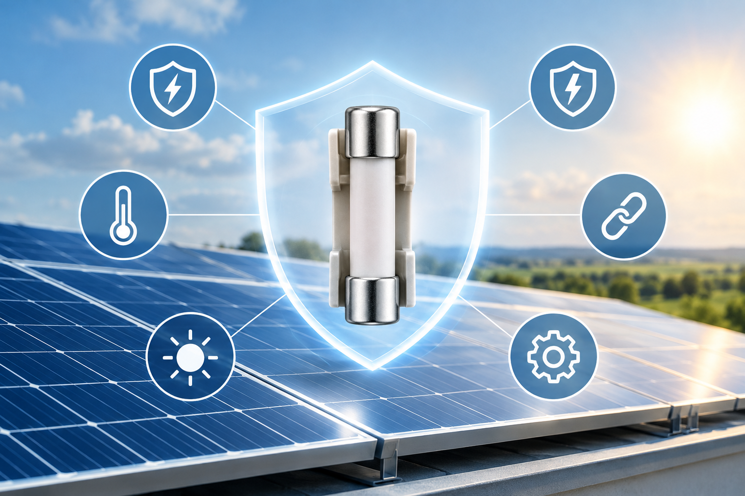
Solar photovoltaic (PV) systems rely on effective electrical protection to ensure safe, reliable, and efficient operation. One common question during solar system design and installation is: Does every PV string need its own fuse?
The answer is no. Not every PV system automatically requires individual string fuses. The need for overcurrent protection depends on several factors, including the number of parallel strings, potential reverse current, module specifications, cable capacity, inverter configuration, and applicable electrical standards.
Understanding when PV string fuses are necessary helps engineers and installers avoid unnecessary components while maintaining adequate system protection.
In this article, we explain how PV string protection works, when fuses are required, and what factors should be considered when selecting the appropriate protection devices.
1. Understanding PV String Fuses
A PV string consists of multiple solar modules connected in series. Several strings can then be connected in parallel to increase the total current supplied to an inverter or combiner box.
During normal operation, each string generates DC electricity and delivers it to the system. However, if a fault occurs in one string, current from other parallel-connected strings may flow backward into the faulty string.
This phenomenon is known as reverse current.
If the reverse current becomes too high, it can cause excessive heating, damage module components, deteriorate cables, and potentially create a fire hazard.
A PV string fuse provides overcurrent protection by interrupting excessive fault current before it causes damage to the system.
However, installing a fuse in every string is not always necessary. The actual requirement depends on the potential fault current and the electrical limits of the system components.
2. Why Does the Number of Parallel Strings Matter?
The number of parallel-connected strings is one of the most important factors when determining whether string fuses are required.
When multiple strings operate in parallel, they can contribute current to a fault occurring in another string.
For example, consider a PV array containing three parallel strings.
If one string develops a short circuit or another electrical fault, the remaining two healthy strings may feed reverse current into the faulty string.
The potential reverse current can increase as more parallel strings are added.
This creates a greater risk of exceeding the maximum reverse current that the solar modules and associated conductors can safely withstand.
Does More Than Two Parallel Strings Always Require Fuses?
A common design guideline suggests that individual string fuses should be considered when more than two strings are connected in parallel.
This is a useful starting point, but it should not be treated as a universal rule.
In a system with two parallel strings, the available reverse current may remain within the permitted limits of the modules. However, this depends on the module specifications and actual system configuration.
Similarly, having three or more parallel strings does not automatically determine the final fuse requirement without considering the available fault current.
Engineers should evaluate:
-
The number of parallel-connected PV strings.
-
The short-circuit current of each solar module.
-
The maximum reverse current permitted by the module.
-
The maximum series fuse rating specified by the module manufacturer.
-
The current-carrying capacity of the string cables.
-
The inverter's internal configuration and potential DC backfeed.
The key principle is that string protection should be based on electrical calculations rather than string count alone.
3. When Might PV String Fuses Not Be Necessary?
There are situations in which individual PV string fuses may not be required.
A separate string fuse may be unnecessary when the maximum possible reverse current remains below the permitted limits of the solar modules and conductors.
Typical examples include:
Single-string PV systems
When only one PV string is connected to an inverter input, there are no other parallel strings available to feed reverse current into a faulty string. Nevertheless, other potential sources of fault current and applicable protection requirements must still be evaluated.
Systems with two parallel strings
In some configurations, the reverse current supplied by the remaining healthy string may be lower than the module's maximum permitted reverse current.
If the module specifications, cable ratings, inverter characteristics, and applicable electrical requirements confirm that additional protection is unnecessary, individual string fuses may not be needed.
Inverter inputs with appropriate isolation
Some inverter configurations provide separate inputs with internal electrical isolation or other design characteristics that limit potential reverse-current paths.
However, installers should never assume that separate inverter inputs automatically eliminate the need for string protection. The inverter manufacturer's technical documentation and the complete system design must be reviewed.
Ultimately, the absence of a string fuse should be supported by a proper engineering assessment.
4. When Are PV String Fuses Necessary?
PV string fuses become particularly important when the potential reverse current exceeds the permissible limits of the connected components.
The following situations require careful evaluation.
Multiple Parallel Strings
When several PV strings share a common electrical connection, the combined current from healthy strings can flow into a faulty string.
As the number of parallel strings increases, the potential reverse current may become sufficient to damage solar modules or cables.
Individual string overcurrent protection may therefore be necessary.
High Reverse Current
If the maximum possible reverse current exceeds the module's permitted reverse current, appropriate overcurrent protection must be provided.
The protection device should interrupt the fault current before it causes thermal or electrical damage.
Limited Cable Current Capacity
String cables must be capable of carrying the maximum current that could occur under normal and fault conditions.
If the combined reverse current exceeds the cable's current-carrying capacity, additional protection may be required.
Cable sizing and overcurrent protection should always be considered together.
Potential Inverter or Battery Backfeed
Some PV installations include energy storage systems or inverter configurations that may introduce additional current paths.
These sources can affect the maximum possible fault current within the DC circuit.
Therefore, engineers should evaluate not only the current contributed by parallel PV strings but also any potential backfeed from connected equipment.
5. How to Determine the Maximum Number of PV Strings Without String Fuses
One practical method of evaluating reverse-current protection is to compare the module's maximum permitted reverse current with its short-circuit current.
A simplified calculation is:
Maximum number of parallel strings without additional reverse-current protection:
Maximum number of strings ≈ Module maximum reverse current ÷ Module short-circuit current
For example, assume the following module specifications:
-
Module short-circuit current (Isc): 8.9 A
-
Module maximum reverse current: 15 A
The calculation is:
15 ÷ 8.9 = 1.69
This indicates that two parallel strings may remain within the assumed reverse-current limit, while three parallel strings could exceed it.
Let's examine the potential fault current.
Two parallel strings:
If one string develops a fault, the remaining healthy string may contribute approximately 8.9 A of reverse current.
This is below the assumed 15 A module limit.
Three parallel strings:
If one string develops a fault, the other two strings may contribute:
2 × 8.9 A = 17.8 A
This exceeds the assumed 15 A limit.
Therefore, additional string overcurrent protection would need to be evaluated and, where required, provided.
Important: This is a simplified illustrative calculation, not a complete fuse-selection method. Actual designs must account for applicable design factors, environmental conditions, inverter backfeed, cable ratings, module specifications, and local electrical regulations.
6. How to Select the Correct PV String Fuse
Determining whether a fuse is necessary is only the first step. Selecting the correct fuse rating and specifications is equally important.
An incorrectly selected fuse may fail to provide adequate protection or interrupt normal operating current unnecessarily.
The following parameters should be considered.
1. Fuse Current Rating
The fuse's rated current must be suitable for the PV string's operating and fault-current characteristics.
It must also coordinate with the module's maximum series fuse rating and the current-carrying capacity of the connected cables.
The maximum series fuse rating specified in the module datasheet is an upper limit, not automatically the recommended fuse rating.
2. DC Voltage Rating
PV systems operate at relatively high DC voltages, particularly in large commercial and utility-scale installations.
The fuse must have a DC voltage rating equal to or greater than the maximum possible system voltage under the applicable design conditions.
Engineers should also consider the increase in open-circuit voltage at low temperatures when determining the maximum string voltage.
3. Breaking Capacity
The fuse must be capable of safely interrupting the maximum prospective fault current.
An insufficient DC breaking capacity can result in dangerous arcing and equipment damage.
Therefore, the fuse's breaking capacity must be checked against the maximum available fault current.
4. Operating Temperature
Solar installations are frequently exposed to high ambient temperatures.
Fuse performance can be affected by enclosure temperature, installation conditions, terminal connections, and heat generated by nearby electrical components.
Appropriate temperature derating and installation requirements should be considered during selection.
5. Compatibility with the Fuse Holder
The fuse link and holder must be electrically and mechanically compatible.
Incorrect dimensions, poor contact pressure, loose connections, or unsuitable holders can cause overheating and unreliable operation.
Using components designed for the intended PV DC application helps maintain safe and stable electrical connections.
7. Do PV String Fuses Reduce Solar System Efficiency?
PV fuses introduce a small amount of electrical resistance into the circuit.
When current flows through a fuse element and its contact points, some electrical energy is converted into heat.
This means that a fuse can introduce a small power loss.
However, in a correctly designed and installed PV system, the additional loss is generally limited.
In practice, installation quality can be more important than the small resistance introduced by the fuse itself.
Potential problems include:
-
Poor electrical contact between the fuse and holder.
-
Loose terminal connections.
-
Incorrectly selected fuse holders.
-
Excessive operating temperatures.
-
Unsuitable fuse ratings.
Installing unnecessary protection devices can add components, cost, and potential connection points without providing a corresponding safety benefit.
On the other hand, removing protection devices that are required by the system design can expose equipment to serious electrical hazards.
The objective should always be to achieve the correct balance between electrical safety, reliability, and system efficiency.
8. What Do Electrical Standards Say About PV String Protection?
PV string protection must comply with the applicable electrical standards and installation regulations in the project location.
For installations following IEC-based requirements, IEC 62548-1 addresses PV array design, including DC wiring and electrical protection considerations.
IEC 60269-6 provides specific requirements for fuse links used to protect photovoltaic strings and arrays.
These requirements help establish the appropriate characteristics of protective devices, including their suitability for PV DC applications.
When selecting PV string fuses, engineers should consider:
-
The maximum DC system voltage.
-
The prospective reverse current.
-
The module's maximum series fuse rating.
-
The current-carrying capacity of the conductors.
-
The fuse's rated current and breaking capacity.
-
The installation environment.
-
Applicable national and local electrical regulations.
It is important to remember that compliance cannot be determined by looking at the number of parallel strings alone.
The complete electrical design must be evaluated before deciding whether individual string fuses are required.
9. What Information Is Needed Before Selecting a PV String Fuse?
A fuse selection should never be based solely on a requested current rating, such as 15 A or 20 A.
The electrical characteristics of the complete PV system must be understood first.
The following information is particularly useful:
| Parameter | Why It Matters |
|---|---|
| Module open-circuit voltage (Voc) | Helps determine maximum string voltage |
| Module short-circuit current (Isc) | Establishes the string current characteristics |
| Number of parallel strings | Helps calculate potential reverse current |
| Maximum DC system voltage | Determines the required fuse voltage rating |
| Maximum series fuse rating | Defines the module's permitted fuse rating limit |
| String cable size | Determines conductor current-carrying capacity |
| Inverter configuration | Helps identify possible reverse-current paths |
| Battery backfeed conditions | Identifies additional potential fault-current sources |
| Ambient temperature | Influences fuse and holder operating conditions |
| Fuse holder dimensions | Ensures mechanical and electrical compatibility |
Providing these details allows engineers to determine whether string protection is necessary and select a suitable protective device.
10. Frequently Asked Questions About PV String Fuses
Does every PV string need an individual fuse?
No. Individual PV string fuses are not automatically required in every installation. Their necessity depends on the potential reverse current, module limitations, cable capacity, inverter configuration, and applicable electrical regulations.
Are fuses mandatory when more than two PV strings are connected in parallel?
Not automatically in every configuration. More than two parallel strings is an important indication that reverse-current protection should be evaluated. The final decision must be based on electrical calculations and applicable requirements.
Can a PV system operate safely without string fuses?
Yes, provided the system design demonstrates that additional string overcurrent protection is not necessary and all other applicable protection requirements are satisfied.
What is the maximum series fuse rating of a solar module?
It is the maximum permitted rating of an overcurrent protection device connected in series with the module. The selected fuse must not exceed the manufacturer's specified limit.
Should both positive and negative PV conductors have fuses?
Not necessarily. The required arrangement depends on the system's grounding configuration, inverter design, and applicable electrical regulations. Protection arrangements should be determined through the system design rather than applying one configuration to every installation.
Do PV string fuses affect system efficiency?
Yes, slightly. Fuse elements and contact points introduce electrical resistance, resulting in a small amount of power loss. However, correctly selected and installed fuses generally have a limited impact on overall PV system efficiency.
What type of fuse should be used in a solar PV system?
The selected fuse should be specifically suitable for photovoltaic DC applications, with appropriate voltage rating, current rating, breaking capacity, and operating characteristics. Fuse selection must also comply with the applicable standards and manufacturer specifications.
Conclusion
So, do PV systems always require fuses for every string?
No. The requirement depends on the electrical characteristics and protection needs of the complete PV installation.
The number of parallel strings is an important consideration, but it is not the only factor. Reverse current, module specifications, conductor capacity, inverter configuration, and potential backfeed must all be evaluated.
In some systems, individual string fuses may be unnecessary because the available reverse current remains within the permitted limits of the connected components. In other installations, particularly those with multiple parallel strings, additional overcurrent protection may be essential.
The most reliable approach is to assess the complete system, calculate the potential fault current, review the module datasheet, and follow the applicable electrical standards.
Ultimately, effective PV protection is not about installing the maximum number of fuses. It is about selecting the right protection devices, in the right locations, to ensure long-term electrical safety, reliability, and performance.
- Details
- Category: Electrical Fuses Blog
| eaton-bussmann-series-photovoltaic-fuses-catalogue-ca135004en.pdf | [Eaton Bussmann PV Fuses] | 0 kB |
Common Mistakes in PV Fuse Selection That Can Lead to System Failure
Introduction
Solar photovoltaic (PV) systems are designed to generate clean, reliable electricity over many years. However, their safety, efficiency, and long-term performance depend on more than just solar panels and inverters. Every electrical protection component plays an important role, and PV fuses are among the most critical.
A properly selected PV fuse protects solar modules, cables, combiner boxes, and other electrical components against overcurrent conditions. It helps prevent equipment damage, overheating, electrical fires, and unexpected system shutdowns.
Despite their importance, mistakes in PV fuse selection are relatively common. Choosing the wrong fuse rating, overlooking voltage requirements, using unsuitable fuse types, or ignoring environmental conditions can compromise the entire solar installation.
In this article, we explore the most common mistakes in PV fuse selection, explain how they can lead to system failure, and discuss practical ways to choose the right fuse for a safe and reliable solar PV system.
1. Selecting the Wrong Current Rating
One of the most common mistakes in PV fuse selection is choosing an incorrect current rating.
A PV fuse must be capable of carrying the normal operating current of the solar circuit while providing protection against excessive current. If the fuse rating is too low, it may blow unnecessarily during normal operation or temporary current variations.
On the other hand, selecting a fuse with an excessively high current rating can prevent it from interrupting dangerous overcurrent conditions quickly enough. This may expose cables, connectors, and solar modules to overheating and potential damage.
How to avoid this mistake:
-
Calculate the maximum expected circuit current before selecting a fuse.
-
Consider the short-circuit current (Isc) of the PV modules.
-
Account for applicable design safety factors and installation conditions.
-
Check conductor ampacity and the maximum series fuse rating specified by the module manufacturer.
-
Follow applicable electrical standards and manufacturer recommendations.
The correct fuse rating should provide reliable protection without causing unnecessary interruptions to normal system operation.
2. Ignoring the Maximum DC Voltage Rating
Solar PV systems operate on direct current (DC), and their voltage can increase significantly under low-temperature conditions.
A common mistake is selecting a fuse based only on the system's nominal operating voltage. The maximum possible open-circuit voltage of the PV string must also be considered.
When temperatures drop, the open-circuit voltage of solar modules generally increases. If the selected fuse has an insufficient DC voltage rating, it may fail to interrupt an electrical fault safely.
DC circuits present a particular challenge because DC arcs do not naturally pass through zero current as AC waveforms do. Consequently, a fuse designed for AC applications may not be suitable for PV DC protection.
How to avoid this mistake:
-
Calculate the maximum PV string open-circuit voltage.
-
Apply the appropriate temperature correction factor.
-
Select a fuse with a DC voltage rating equal to or greater than the maximum calculated system voltage.
-
Verify that the fuse is specifically designed and approved for photovoltaic applications.
Never assume that an AC fuse with a similar current rating can safely replace a DC-rated PV fuse.
3. Using Standard Fuses Instead of PV-Specific Fuses
Not all fuses are designed to handle the electrical characteristics of solar photovoltaic systems.
Standard electrical fuses may not provide the necessary performance under the prolonged operating conditions and fault characteristics associated with PV installations.
PV systems can experience relatively low overcurrent fault levels compared with conventional electrical distribution systems. As a result, the fuse must have suitable operating characteristics to interrupt these faults reliably.
Using a general-purpose fuse instead of a dedicated photovoltaic fuse can result in delayed operation, inadequate fault interruption, or unsafe failure.
How to avoid this mistake:
-
Choose fuses specifically designed for photovoltaic applications.
-
Verify compliance with the relevant PV fuse standard, such as IEC 60269-6.
-
Check the fuse's rated voltage, current, breaking capacity, and operating characteristics.
-
Ensure compatibility with the PV system's electrical configuration.
Using a purpose-designed PV fuse helps ensure dependable protection under the operating conditions of solar installations.
4. Overlooking Breaking Capacity
Breaking capacity, also known as interrupting capacity, refers to the maximum fault current a fuse can safely interrupt at its rated voltage.
Ignoring this specification can create a serious safety risk.
If a fault generates a current higher than the fuse's breaking capacity, the fuse may not interrupt the current safely. This can lead to arcing, overheating, physical damage, or even an electrical fire.
In PV systems, the available fault current must be assessed based on the circuit configuration and the possible contribution from parallel-connected strings.
How to avoid this mistake:
-
Calculate or determine the maximum prospective short-circuit current.
-
Select a fuse with an adequate DC breaking capacity.
-
Consider the number of parallel-connected PV strings.
-
Verify the fuse's interrupting performance at the actual system voltage.
Breaking capacity should never be treated as a secondary specification. It is essential for safe fault interruption.
5. Choosing the Wrong Fuse Size or Holder
Even when the electrical specifications are correct, selecting an incompatible fuse size or holder can compromise system safety.
PV fuses are available in different physical dimensions and configurations. The fuse must fit securely into its designated fuse holder or protection assembly.
Using an incorrectly sized fuse can result in loose connections, poor electrical contact, increased contact resistance, and excessive heat generation.
These problems can gradually damage the fuse holder and surrounding components, potentially causing system downtime or fire hazards.
How to avoid this mistake:
-
Check the required fuse dimensions before purchasing.
-
Ensure compatibility between the fuse and fuse holder.
-
Verify the rated current and voltage of both components.
-
Use suitable connection terminals and installation accessories.
-
Follow the manufacturer's installation instructions.
Correct physical compatibility is just as important as electrical compatibility.
6. Ignoring Temperature and Environmental Conditions
Solar installations are frequently exposed to demanding environmental conditions, including high temperatures, humidity, dust, UV radiation, and outdoor weather exposure.
A common mistake is selecting PV fuses without considering the environment in which they will operate.
High ambient temperatures can affect fuse performance and may require derating according to manufacturer specifications. Similarly, inadequate protection against moisture, dust, and corrosion can damage fuse holders and electrical connections.
When these environmental factors are overlooked, fuse reliability may decrease, resulting in premature failure or inconsistent protection.
How to avoid this mistake:
-
Consider the maximum expected ambient temperature.
-
Apply manufacturer-specified temperature derating where required.
-
Use compatible fuse holders with suitable environmental protection.
-
Ensure the installation enclosure provides appropriate protection against dust and moisture.
-
Inspect connections periodically for corrosion, discoloration, and overheating.
Environmental suitability should be considered during the initial design stage rather than after installation problems occur.
7. Neglecting PV String Configuration
The electrical configuration of a solar PV array directly influences fuse selection.
A PV array may contain multiple strings connected in parallel. Under certain fault conditions, current from healthy parallel strings can flow into a faulty string, creating potentially damaging reverse current.
If the appropriate string overcurrent protection is not installed, solar modules, cables, and connectors may be exposed to excessive current.
Another common mistake is assuming that every PV string requires identical protection without evaluating the system's actual configuration.
How to avoid this mistake:
-
Understand the number of strings connected in parallel.
-
Evaluate possible reverse-current conditions.
-
Check the module's maximum series fuse rating.
-
Determine whether string-level overcurrent protection is required.
-
Follow the system design requirements and applicable electrical standards.
Proper coordination between string configuration and fuse protection is essential for preventing reverse-current damage.
8. Ignoring Relevant Standards and Certification Requirements
PV fuse selection should never rely solely on price, appearance, or basic electrical ratings.
Using products without appropriate testing, certification, or compliance documentation can introduce unnecessary risks into a solar installation.
Different PV systems have different operating requirements, and the selected fuse must meet the relevant technical and safety standards.
For photovoltaic applications, IEC 60269-6 is an important standard covering fuse-links for solar photovoltaic energy systems.
How to avoid this mistake:
-
Check compliance with applicable PV fuse standards.
-
Verify technical documentation and certification.
-
Review rated voltage, rated current, and breaking capacity.
-
Confirm that the fuse is suitable for the intended PV application.
-
Purchase components with traceable specifications and quality documentation.
Compliance helps ensure that the selected fuse has been designed and tested for its intended application.
9. Focusing Only on Initial Purchase Cost
Cost is an important consideration in solar project planning. However, choosing the cheapest available PV fuse without evaluating its quality and performance can become an expensive mistake.
Low-quality components may have inconsistent electrical characteristics, poor manufacturing quality, or inadequate long-term reliability.
A fuse that fails prematurely can result in maintenance expenses, system downtime, equipment damage, and additional replacement costs.
In severe cases, inadequate protection can contribute to significant electrical safety incidents.
How to avoid this mistake:
-
Evaluate technical specifications rather than price alone.
-
Check manufacturing quality and relevant certifications.
-
Consider expected service life and operating conditions.
-
Assess the total cost of ownership.
-
Choose products that meet the system's safety and reliability requirements.
A suitable PV fuse is an investment in the long-term performance and safety of the solar installation.
10. Failing to Inspect and Maintain PV Fuse Connections
Correct fuse selection is only one part of effective PV system protection. Improper installation and insufficient maintenance can also lead to system failure.
Over time, electrical connections may loosen, contact resistance may increase, and corrosion or thermal damage may develop.
A fuse that was correctly selected during installation may therefore become part of an unreliable protection assembly if its holder and connections are neglected.
How to avoid this mistake:
-
Include fuse holders and connections in routine maintenance inspections.
-
Look for signs of overheating, corrosion, or physical damage.
-
Check electrical connections according to manufacturer procedures.
-
Replace damaged or deteriorated components with compatible parts.
-
Use qualified personnel for inspection and maintenance.
Routine inspection helps identify developing problems before they cause serious system failures.
Best Practices for Selecting the Right PV Fuse
Avoiding common PV fuse selection mistakes requires a systematic approach. Before choosing a fuse for a solar installation, engineers, installers, and system designers should evaluate the following parameters:
| Selection parameter | What to verify |
|---|---|
| Rated current | Suitable for the maximum expected operating current |
| Rated DC voltage | Equal to or greater than the maximum corrected PV string voltage |
| Breaking capacity | Adequate for the maximum prospective fault current |
| Fuse type | Specifically designed for photovoltaic applications |
| Standard compliance | Meets relevant PV fuse requirements, including IEC 60269-6 |
| Physical dimensions | Compatible with the fuse holder |
| Temperature rating | Suitable for actual operating conditions |
| String configuration | Appropriate for parallel-string and reverse-current protection |
| Module compatibility | Does not exceed the module's maximum series fuse rating |
A careful evaluation of these parameters helps reduce electrical risks, improve protection coordination, and support reliable solar power generation.
Conclusion
PV fuse selection is a critical part of designing a safe and dependable solar photovoltaic system. Even a seemingly minor selection error can lead to unnecessary fuse operation, inadequate fault protection, overheating, equipment damage, or complete system failure.
The most common mistakes include choosing incorrect current and voltage ratings, using non-PV-specific fuses, overlooking breaking capacity, ignoring environmental conditions, and neglecting system configuration and maintenance requirements.
By understanding these risks and following the relevant technical standards, solar installers and system designers can make better fuse selection decisions.
Ultimately, the right PV fuse does more than protect an electrical circuit. It helps safeguard valuable solar equipment, reduce maintenance costs, minimize downtime, and ensure the long-term safety and reliability of photovoltaic installations.
Frequently Asked Questions (FAQs)
1. What is the most common mistake in PV fuse selection?
One of the most common mistakes is selecting an incorrect fuse current rating. A fuse with an unsuitable rating may blow unnecessarily or fail to provide adequate protection against dangerous overcurrent conditions.
2. Why are PV-specific fuses necessary?
PV-specific fuses are designed to handle the electrical characteristics of solar photovoltaic systems, including DC operation and the fault conditions associated with PV arrays. They provide more appropriate protection than general-purpose fuses.
3. What standard applies to photovoltaic fuses?
IEC 60269-6 is a key international standard covering fuse-links for solar photovoltaic energy systems. It addresses requirements relevant to the safe operation of PV fuses.
4. Can an AC fuse be used in a solar PV system?
An AC fuse should not automatically be used in a DC photovoltaic circuit. DC applications require appropriate voltage and interruption ratings because DC arcs can be more difficult to extinguish. Always select a fuse specifically rated for the intended PV DC application.
5. What happens if a PV fuse has an excessively high current rating?
An excessively high fuse rating may prevent the fuse from operating quickly enough during an overcurrent fault. This can expose solar modules, cables, and other components to overheating and damage.
6. How do I determine the correct PV fuse rating?
Consider the module short-circuit current, the maximum expected operating current, system configuration, conductor ampacity, module maximum series fuse rating, and applicable design requirements. Always follow the relevant standards and manufacturer specifications.
7. How often should PV fuses be inspected?
PV fuses and their connections should be included in a regular preventive maintenance programme. Inspection frequency should reflect the installation environment, system operating conditions, and manufacturer recommendations. Any inspection or replacement should be carried out by qualified personnel.
- Details
- Category: Electrical Fuses Blog
| eaton-bussmann-series-high-speed-fuses-application-guide-br132015en-en-us.pdf | [Eaton Bussmann Fuses Technical Guide] | 0 kB |
| eaton-bussmann-series-photovoltaic-fuses-catalogue-ca135004en.pdf | [Eaton Bussmann PV Fuses] | 0 kB |
Ceramic or Melamine Fuse Tubes? Understanding the Differences and Choosing the Right Material
When selecting a fuse for photovoltaic (PV) systems, industrial applications or high-voltage DC circuits, the material of the fuse tube is an important factor to consider. Two commonly used materials are ceramic and glass-fibre-reinforced melamine. Although both provide electrical insulation and help protect the internal components of a fuse, they differ in their mechanical properties, impact resistance and practical applications.
So, which is better: ceramic or melamine fuse tubes?
The answer depends on the operating environment, electrical requirements and overall fuse construction. Understanding the differences between these materials can help engineers, installers and purchasing professionals make informed decisions when selecting the right fuse for their applications.
What Is a Fuse Tube and Why Does Its Material Matter?
A fuse tube is an essential component of a cartridge fuse. It surrounds the internal fuse element and provides electrical insulation while containing the heat and pressure generated during the interruption of an electrical fault.
A typical high-voltage DC photovoltaic fuse consists of several components:
-
Fuse element: A precisely designed metal conductor that melts when excessive current flows through the circuit.
-
Insulating tube: Provides electrical insulation and contains the internal arc during fuse operation.
-
Metal end caps: Connect the fuse to the electrical circuit.
-
Quartz sand: Absorbs heat and helps extinguish the electrical arc.
When a short circuit occurs, the fuse element melts and creates an electrical arc. Quartz sand absorbs energy and helps transform the arc into a high-resistance path, allowing the current to be interrupted safely.
The fuse tube must withstand the resulting temperature and internal pressure without cracking or losing its insulating properties.
This is particularly important in 1000VDC and 1500VDC photovoltaic systems, where interrupting a DC fault can be challenging.
Therefore, the choice of fuse tube material is not simply an aesthetic or manufacturing consideration. It contributes to the overall safety, reliability and performance of the fuse.
1. Ceramic Fuse Tubes: Advantages and Disadvantages
Ceramic has been used in electrical fuse manufacturing for many years. It is widely recognised for its excellent thermal stability, electrical insulation and dimensional consistency.
Advantages of Ceramic Fuse Tubes
Excellent heat resistance
Ceramic materials can withstand high operating temperatures, making them suitable for demanding electrical applications. Their thermal stability helps maintain the structural integrity of the fuse during operation.
Reliable electrical insulation
Ceramic provides excellent dielectric properties, helping prevent unwanted current leakage and electrical breakdown.
Proven performance
Ceramic fuse tubes have a long history of use in industrial electrical equipment and various types of high-voltage fuse applications.
Dimensional stability
Ceramic maintains its shape and dimensions under normal operating conditions, supporting consistent manufacturing and assembly.
Disadvantages of Ceramic Fuse Tubes
Despite their advantages, ceramic fuse tubes have one important limitation: brittleness.
Although ceramic is strong, it can crack or break when subjected to mechanical impact. Damage may occur during transportation, installation or handling.
In some cases, small cracks may not be immediately visible. Such damage can potentially compromise the insulation and mechanical integrity of the fuse.
For this reason, ceramic fuse tubes require careful handling, particularly in applications involving long-distance transportation or environments exposed to vibration.
However, this does not mean ceramic fuses are inherently unsafe. A properly manufactured and tested ceramic fuse can provide reliable performance when its complete construction meets the required electrical and mechanical specifications.
2. Melamine Fuse Tubes: Advantages and Disadvantages
Glass-fibre-reinforced melamine is an alternative material used in certain high-voltage DC fuse applications.
Unlike ordinary plastic, this material is a thermosetting composite reinforced with glass fibres. The reinforcement improves its mechanical strength and impact resistance.
Advantages of Melamine Fuse Tubes
Better impact resistance
One of the main advantages of glass-fibre-reinforced melamine is its toughness. Compared with conventional ceramic tubes, it generally offers better resistance to mechanical impacts.
This can reduce the risk of damage during transportation, storage and installation.
Lower risk of brittle cracking
Melamine composite materials are less prone to brittle fracture than ceramic. This makes them particularly useful in applications where mechanical handling conditions are difficult to control.
Lightweight construction
Melamine fuse tubes are relatively lightweight, which can be beneficial for transportation, handling and manufacturing.
Good electrical insulation
Glass-fibre-reinforced melamine provides suitable electrical insulation properties for properly designed and tested fuse applications.
Heat resistance and flame-retardant properties
As a thermosetting composite, reinforced melamine can offer good thermal stability and flame resistance when manufactured using an appropriate material formulation.
Disadvantages of Melamine Fuse Tubes
Although melamine offers several mechanical advantages, its performance depends on the quality of the material and manufacturing process.
Factors such as glass-fibre content, resin formulation, curing conditions and tube wall thickness can influence the final properties.
Furthermore, using a melamine tube does not automatically guarantee superior fuse performance.
The fuse element, quartz sand filling, end-cap connections and overall arc-extinguishing design must all work together to ensure reliable fault interruption.
Consequently, buyers should evaluate the complete fuse rather than selecting a product based solely on its tube material.
3. Ceramic vs. Melamine Fuse Tubes: Key Differences
Understanding the differences between ceramic and glass-fibre-reinforced melamine makes it easier to determine which material is more appropriate for a particular electrical application.
| Comparison | Ceramic Fuse Tube | Melamine Fuse Tube |
|---|---|---|
| Heat resistance | Excellent | Good |
| Electrical insulation | Excellent | Good |
| Mechanical strength | Strong but brittle | Strong and tough |
| Impact resistance | Relatively low | Generally higher |
| Risk of cracking | Higher under mechanical impact | Lower under mechanical impact |
| Weight | Relatively heavier | Relatively lighter |
| Thermal stability | Excellent | Good |
| Handling requirements | Requires careful handling | Generally more impact tolerant |
| Typical applications | Industrial and electrical protection | High-voltage DC and applications requiring improved impact resistance |
Both materials can be suitable for electrical protection applications when the fuse is correctly engineered and tested.
The primary difference is their mechanical behaviour. Ceramic offers established thermal and insulating performance, while glass-fibre-reinforced melamine provides an advantage in impact resistance and handling durability.
4. Which Fuse Tube Is Better for Solar PV Systems?
Solar photovoltaic systems operate under specific electrical and environmental conditions. As solar installations increasingly use 1000VDC and 1500VDC architectures, selecting the correct fuse becomes especially important.
PV fuses are commonly installed in combiner boxes, inverters and DC distribution equipment. They must provide reliable protection against overcurrent and short-circuit faults.
Both ceramic and melamine fuse tubes can be used in appropriately designed photovoltaic fuse links.
However, the application environment can influence which material is preferable.
When to Choose Ceramic Fuse Tubes
Ceramic fuse tubes can be a suitable choice when:
-
The installation environment is relatively stable.
-
Mechanical impact is unlikely.
-
Transportation and handling conditions are well controlled.
-
The fuse has demonstrated the required breaking capacity.
-
The product meets the applicable electrical and safety standards.
For established industrial applications and controlled installation environments, ceramic remains a practical and proven material.
When to Choose Melamine Fuse Tubes
Glass-fibre-reinforced melamine may be preferable when:
-
The fuse will undergo long-distance transportation.
-
Mechanical vibration is expected.
-
Installation involves frequent handling.
-
Improved impact resistance is desirable.
-
The application requires a lightweight fuse construction.
For large-scale solar installations, where equipment may travel long distances before reaching the installation site, improved mechanical toughness can be a practical advantage.
Nevertheless, the final selection should always be based on verified technical specifications and performance testing.
5. Why Are 1500VDC PV Fuses Different from 1000VDC Fuses?
The operating voltage is another critical consideration when selecting a photovoltaic fuse.
Interrupting a DC electrical arc is generally more challenging than interrupting an AC arc because DC current does not naturally pass through zero during each cycle.
As system voltage increases, the fuse must manage greater electrical stress and provide effective arc extinction.
This is why 1500VDC photovoltaic fuses often have different dimensions and internal structures compared with conventional 1000VDC fuse links.
Common cylindrical fuse dimensions include:
-
10 × 38 mm
-
14 × 51 mm
-
22 × 58 mm
-
10 × 65 mm
-
10 × 85 mm
-
14 × 85 mm
Longer fuse bodies can provide additional internal space for arc division and cooling, as well as suitable insulation distances.
However, a longer fuse is not automatically suitable for a higher-voltage application. The fuse element geometry, quartz sand distribution, tube construction and end-cap design must all be engineered for the intended voltage and breaking capacity.
It is also essential to ensure that the fuse dimensions match the corresponding fuse holder.
6. Important Factors to Consider When Selecting a PV Fuse
Whether choosing a ceramic or melamine fuse tube, the material should never be the only selection criterion.
The following technical factors are equally important.
Rated Voltage
The rated voltage of the fuse must be equal to or greater than the maximum possible system voltage.
For photovoltaic installations, the maximum open-circuit voltage should be calculated by considering the number of modules connected in series, module voltage specifications and the lowest expected operating temperature.
A 1000VDC fuse must not be used in a 1500VDC system simply because its current rating is suitable.
Rated Current
The fuse current rating should be selected according to the module short-circuit current, manufacturer's maximum series fuse rating, cable capacity and system design.
Ambient temperature and installation conditions should also be considered.
An incorrectly selected fuse rating may result in unnecessary fuse operation or inadequate circuit protection.
Breaking Capacity
Breaking capacity is one of the most important specifications of a high-voltage DC fuse.
It indicates the maximum prospective fault current that the fuse can safely interrupt under specified test conditions.
A suitable PV fuse must have a verified breaking capacity appropriate for the electrical system.
gPV Utilization Category
Photovoltaic fuse links should be designed for the specific requirements of PV circuit protection.
The gPV utilization category is particularly relevant when selecting fuses for solar applications.
Relevant standards include IEC 60269-6 and UL 248-19. Buyers should verify that the exact fuse model complies with the applicable requirements.
Fuse Holder Compatibility
A fuse must be mechanically and electrically compatible with its holder.
Important considerations include:
-
Fuse dimensions.
-
Rated voltage and current.
-
Contact design.
-
Terminal connections.
-
Temperature rise.
-
Permitted conductor sizes.
Using a fuse with the wrong dimensions or unsuitable contact arrangement can cause overheating and unreliable electrical connections.
7. Why the Complete Fuse Design Matters More Than Tube Material
One common mistake when purchasing photovoltaic fuses is focusing exclusively on whether the fuse tube is ceramic or melamine.
Although the tube material is important, the overall fuse construction determines its actual performance.
A reliable high-voltage DC fuse requires several components to function together:
Fuse element design: The element must have precisely controlled dimensions and melting characteristics to provide the intended protection.
Quartz sand filling: The quantity, particle properties and distribution of quartz sand influence heat absorption and arc extinction.
Fuse tube construction: The tube must withstand the temperature and internal pressure generated during fault interruption.
End-cap connections: Secure electrical connections are essential for minimising contact resistance and preventing excessive heating.
Testing and certification: Electrical performance must be verified under the relevant standards and test conditions.
A fuse with a high-quality tube but poorly designed internal components may still fail to provide reliable protection.
For this reason, engineers and purchasing professionals should request complete technical documentation rather than evaluating products based on material descriptions alone.
8. Frequently Asked Questions About Ceramic and Melamine Fuse Tubes
Is a ceramic fuse tube better than a melamine fuse tube?
Neither material is universally better. Ceramic offers excellent thermal stability and established insulating performance, while glass-fibre-reinforced melamine generally provides better impact resistance and mechanical toughness.
The appropriate choice depends on the installation environment and the complete fuse design.
Are melamine fuse tubes made of plastic?
Not exactly. High-voltage DC fuse tubes described as melamine are typically manufactured from thermosetting melamine composite reinforced with glass fibres.
This is different from ordinary plastic and provides improved mechanical strength, electrical insulation and thermal properties.
Are ceramic fuse tubes suitable for 1500VDC photovoltaic systems?
Yes. Properly designed and tested ceramic fuse links can be suitable for 1500VDC photovoltaic applications.
The rated voltage, breaking capacity, internal construction and relevant certifications must be verified for the exact fuse model.
Why are melamine fuse tubes more resistant to impact?
Glass-fibre reinforcement improves the mechanical toughness of the thermosetting composite. This helps reduce the likelihood of brittle cracking compared with conventional ceramic materials.
Can I replace a ceramic fuse with a melamine fuse?
A replacement should not be selected based on tube material alone.
The replacement fuse must have compatible voltage and current ratings, breaking capacity, utilization category, dimensions and electrical characteristics.
Always verify compatibility with the existing fuse holder and the requirements of the electrical system.
Are transparent glass fuses suitable for solar PV systems?
Transparent glass fuses are commonly used in electronic equipment and low-current control circuits.
They are generally not appropriate substitutes for dedicated 1000VDC or 1500VDC photovoltaic fuse links because their construction and arc-interruption capabilities may not meet the requirements of high-voltage PV protection.
Conclusion: Choosing the Right Fuse Tube Material
The choice between ceramic and melamine fuse tubes depends on the specific requirements of the electrical application.
Ceramic fuse tubes offer excellent thermal stability, reliable insulation and a long history of use in electrical protection equipment. They are suitable for many industrial and photovoltaic applications when correctly designed and tested.
Glass-fibre-reinforced melamine fuse tubes provide improved impact resistance, reduced brittleness and relatively lightweight construction. These properties make them particularly attractive for photovoltaic applications involving long-distance transportation, mechanical vibration or demanding handling conditions.
However, the most important consideration is not simply the tube material. Rated voltage, rated current, breaking capacity, gPV classification, internal fuse construction and verified certification must all be evaluated together.
By considering these factors, engineers, installers and purchasing professionals can select photovoltaic fuses that provide reliable electrical protection, long-term performance and improved system safety.