
Electrical Fuses Blog
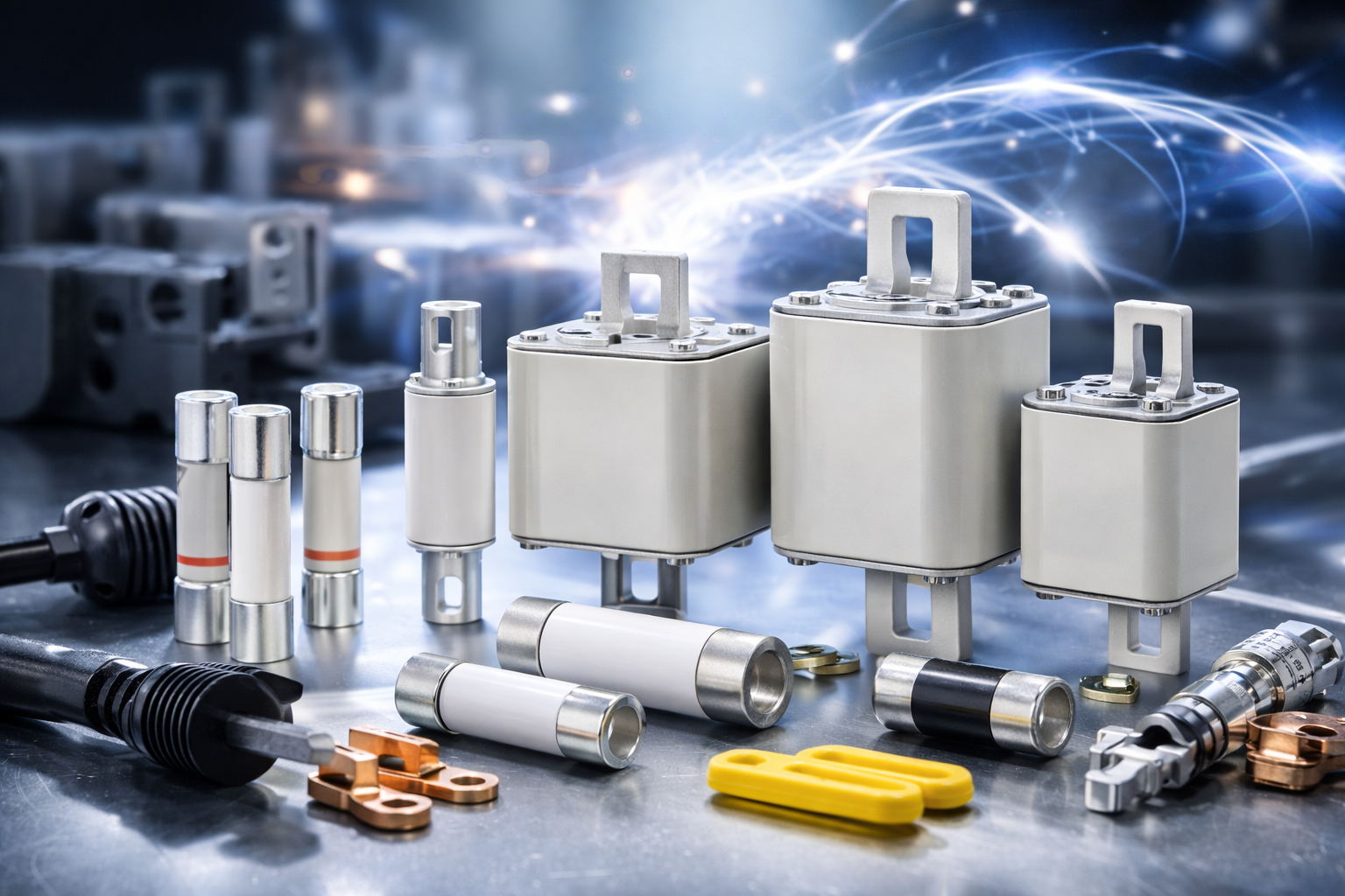
Eaton Bussmann Series Electrical Fuses – Blog & Fachwissen
Im Eaton Bussmann Series Electrical Fuses Blog finden Sie fundiertes Fachwissen rund um elektrische Sicherungen, Überstromschutz und moderne Schutzkonzepte für industrielle und gewerbliche Anwendungen. Diese Kategorie bündelt alle Blogartikel, technischen Beiträge und Praxisguides zu den Sicherungssystemen und Serien von Eaton Bussmann.
Eaton Bussmann zählt weltweit zu den führenden Herstellern von elektrischen Sicherungen, und ihre Serien stehen für Sicherheit, Normkonformität und höchste Zuverlässigkeit in anspruchsvollen elektrischen Systemen.
Was Sie im Eaton Bussmann Sicherungen Blog erwartet
Unsere Blogbeiträge helfen Ingenieuren, Einkäufern, Technikern und Planern dabei, die richtige Sicherungslösung zu finden und technische Zusammenhänge besser zu verstehen.
Themenschwerpunkte dieser Kategorie:
-
🔌 Überblick über Eaton Bussmann Sicherungsserien
-
⚙️ Unterschiede zwischen UL-, IEC- und Spezial-Sicherungen
-
📘 Technische Erklärungen zu Kennlinien, Auslöseverhalten & Bemessungswerten
-
🏭 Anwendungstipps für Industrie, Maschinenbau & Energieverteilung
-
🚗 Beiträge zu EV-, DC- und Hochvolt-Sicherungen
-
🛠 Best Practices für Auswahl, Installation und Wartung
Alle Inhalte sind praxisnah, verständlich aufbereitet und technisch fundiert.
Eaton Bussmann Sicherungsserien im Fokus
Der Blog behandelt regelmäßig verschiedene Eaton Bussmann Series Electrical Fuses, darunter:
-
Industrial Fuses
-
North American (UL) Fuse Series
-
IEC Sicherungsserien
-
High Speed & Semiconductor Fuses
-
EV & DC Sicherungen
-
Supplementary & Specialty Fuses
So erhalten Sie einen umfassenden Überblick über das Eaton Bussmann Portfolio und dessen Einsatzmöglichkeiten.
Fachwissen für sichere elektrische Systeme
Elektrische Sicherungen sind ein zentraler Bestandteil jeder sicheren Stromversorgung. Der Eaton Bussmann Series Electrical Fuses Blog unterstützt Sie dabei, Risiken zu minimieren, Normen einzuhalten und die Lebensdauer Ihrer Anlagen zu verlängern.
Ganz gleich, ob Sie Grundlagenwissen suchen oder tief in spezielle Sicherungsserien eintauchen möchten – hier finden Sie relevante, aktuelle und suchmaschinenoptimierte Inhalte rund um Eaton Bussmann Electrical Fuses.
👉 Jetzt Blogartikel entdecken und Ihr Wissen über Eaton Bussmann Sicherungsserien gezielt erweitern.
- Details
- Category: Electrical Fuses Blog
 eaton-bussmann-series-dc-fuses-catalog-ca135009en-us.pdf  | [Eaton Bussmann DC Fuses] | 0 kB |
| eaton-bussmann-series-photovoltaic-fuses-catalogue-ca135004en.pdf | [Eaton Bussmann PV Fuses] | 0 kB |
The Deep Link Between Solar PV and Energy Storage: How Integrated Systems Create a More Reliable Energy Future
Introduction
The global transition towards renewable energy is accelerating, and solar photovoltaic (PV) technology is playing an increasingly important role in modern electricity generation. However, generating clean electricity is only one part of the energy equation. To maximise the benefits of solar power, energy storage systems (ESS) have become an essential component of modern renewable energy infrastructure.
The relationship between solar PV and energy storage goes far beyond simply generating and storing electricity. Together, these technologies create an integrated energy solution that improves efficiency, increases energy independence, reduces electricity costs, and strengthens power system reliability.
Whether used in residential installations, commercial buildings, industrial facilities, or large-scale solar farms, combining solar PV with battery energy storage systems (BESS) provides greater control over how electricity is generated, distributed, stored, and consumed.
In this guide, we explore the connection between solar PV and energy storage, how integrated systems operate, their key advantages, essential electrical protection components, and the factors to consider when designing a safe and efficient solar-plus-storage installation.
1. Understanding the Relationship Between Solar PV and Energy Storage
Solar photovoltaic systems convert sunlight directly into electrical energy through semiconductor solar cells. During daylight hours, solar panels generate direct current (DC) electricity, which is typically converted into alternating current (AC) through an inverter for use by electrical appliances and equipment.
However, solar energy generation is naturally dependent on weather conditions and daylight availability. Electricity production often reaches its highest levels during midday, while household and commercial electricity consumption may peak in the morning and evening.
This creates a mismatch between energy generation and demand.
Energy storage systems help overcome this challenge by storing surplus electricity generated during periods of high solar production and releasing it when solar generation decreases or electricity demand increases.
The integration of solar PV and battery storage creates a more flexible energy system with several important functions:
-
Energy storage: Excess solar electricity is stored in batteries instead of being wasted or exported to the grid.
-
Peak shaving: Stored energy can be used during periods of high electricity demand.
-
Load shifting: Electricity generated during the day can be consumed later.
-
Backup power: Compatible systems can provide electricity during grid interruptions.
-
Grid stabilisation: Battery systems can support frequency regulation, voltage control, and other grid services.
The result is a renewable energy system that offers greater flexibility and more effective energy management.
2. How Solar PV and Battery Energy Storage Systems Work Together
Understanding how solar PV and battery storage interact is essential for designing an efficient integrated system.
A typical solar-plus-storage installation consists of several interconnected components.
Solar PV Modules
Solar panels capture sunlight and generate DC electricity. Multiple panels are connected into strings to achieve the required voltage and current levels.
The electrical output depends on several factors, including sunlight intensity, panel orientation, temperature, shading, and system configuration.
PV Combiner Boxes
PV combiner boxes collect electricity from multiple solar panel strings and combine their outputs into fewer electrical connections.
They also provide important protection and monitoring functions, including:
-
Individual string overcurrent protection.
-
DC fuse installation.
-
Surge protection.
-
DC isolation.
-
String-level monitoring.
Properly designed combiner boxes help simplify system wiring while improving electrical safety and maintenance efficiency.
Solar Inverters
Solar inverters convert DC electricity generated by solar panels into AC electricity suitable for electrical loads and grid connection.
In hybrid installations, compatible inverters also manage the interaction between solar generation, battery charging, battery discharging, and grid electricity.
Battery Energy Storage Systems
Battery energy storage systems store electrical energy for later use.
During periods of strong sunlight, surplus solar electricity can charge the battery. When solar production falls or electricity demand rises, the stored energy can be discharged to supply connected loads.
Battery systems typically include battery modules, a battery management system (BMS), power conversion equipment, monitoring functions, and electrical protection devices.
Energy Management Systems
An energy management system coordinates electricity generation, storage, and consumption.
Depending on system configuration, it can determine when to charge batteries, when to discharge stored electricity, and when to draw power from the grid.
This intelligent coordination helps improve overall system performance and energy utilisation.
3. Why Solar PV and Energy Storage Are Better Together
Combining solar PV with battery storage provides several advantages that individual technologies cannot deliver as effectively on their own.
Improved Solar Energy Self-Consumption
Without battery storage, surplus electricity generated during the day may need to be exported to the grid.
With an integrated storage system, excess electricity can be stored and used later.
This increases the proportion of locally generated solar energy consumed directly by a home or business.
Reduced Electricity Costs
Electricity prices can vary depending on the time of day and overall demand.
Battery storage allows users to store electricity when solar generation is high and use it during more expensive peak periods.
This can reduce electricity purchases from the grid and improve the financial performance of solar installations.
Actual savings depend on electricity tariffs, battery efficiency, system sizing, and local energy regulations.
Greater Energy Independence
Solar panels reduce dependence on conventional electricity generation, while battery storage allows users to retain surplus energy for later consumption.
Together, they provide greater control over electricity supply and reduce exposure to grid electricity price fluctuations.
Improved Power Reliability
Battery energy storage can provide backup electricity during grid outages when the system is specifically designed for backup operation.
This is particularly valuable for critical commercial processes, industrial facilities, communication infrastructure, and essential household equipment.
Better Grid Integration
Large-scale battery systems can help balance fluctuations in renewable energy generation.
They can respond to changing electricity demand, support grid frequency and voltage management, and reduce pressure on electrical infrastructure.
4. The Importance of Electrical Protection in Solar PV and Energy Storage Systems
Although integrating solar PV with battery storage offers significant benefits, it also introduces additional electrical complexity.
Modern renewable energy installations can involve high DC voltages, substantial fault currents, bidirectional power flows, and multiple interconnected electrical circuits.
These conditions make electrical protection a fundamental part of system design.
An appropriately engineered protection strategy helps prevent equipment damage, minimise electrical hazards, and maintain reliable operation.
DC Fuses for Solar PV String Protection
Solar PV strings require suitable overcurrent protection to help prevent damage caused by reverse currents and electrical faults.
DC photovoltaic fuses are designed to interrupt fault currents under the specific operating conditions of solar installations.
When selecting a PV fuse, engineers should consider:
-
Maximum system DC voltage.
-
Maximum operating current.
-
Prospective short-circuit current.
-
Fuse breaking capacity.
-
Operating temperature.
-
Applicable photovoltaic fuse standards.
The selected fuse must be appropriate for the electrical characteristics of the installation.
Battery Energy Storage Fuses
Battery energy storage systems have different electrical characteristics from conventional solar PV strings.
Battery packs can deliver substantial fault currents, and their charging and discharging operation introduces additional protection considerations.
Battery protection fuses must therefore be selected according to battery voltage, maximum operating current, prospective fault current, and the required interruption characteristics.
Correct fuse selection helps protect battery modules, DC distribution circuits, and power conversion equipment.
Importantly, a fuse designed for PV string protection should not automatically be assumed suitable for battery applications.
Surge Protection Devices
Lightning strikes and switching operations can produce electrical surges that damage sensitive equipment.
Surge protection devices (SPDs) help limit transient overvoltages and protect inverters, monitoring equipment, and other connected electrical components.
The selection and installation of SPDs should consider the system voltage, grounding arrangement, lightning protection strategy, and applicable electrical standards.
DC Isolator Switches
DC isolator switches allow electrical circuits to be disconnected for inspection, maintenance, and emergency procedures.
Because DC circuits can sustain electrical arcs when interrupted, isolators must be specifically rated for the intended DC voltage and current.
Correct installation and operation are essential for maintenance safety.
Fuse Holders and Fuse Bases
Fuse holders provide the mechanical and electrical connection between fuse links and the protected circuit.
They must be compatible with the selected fuse dimensions, voltage ratings, current ratings, and installation environment.
High-quality fuse holders also support reliable electrical connections, effective heat management, and safe fuse replacement.
5. Key Differences Between Solar PV Protection and Battery Storage Protection
Although solar PV and battery energy storage systems are frequently integrated, their electrical protection requirements are not identical.
Understanding these differences is essential for selecting appropriate components.
| Technical factor | Solar PV systems | Battery storage systems |
|---|---|---|
| Main energy source | Solar-generated electricity | Stored electrical energy |
| Current characteristics | Dependent on solar irradiance and array configuration | Can deliver high fault currents |
| Power flow | Generally from PV modules towards the inverter | Charging and discharging |
| Main protection focus | String and DC circuit protection | Battery modules, racks, and DC buses |
| Common protection devices | PV DC fuses, SPDs, isolators | Battery DC fuses, circuit breakers, isolators |
| Design considerations | PV voltage, string current, reverse-current protection | Battery fault current, charge/discharge profiles, interruption capacity |
One of the most important considerations is that battery systems can produce high fault currents even when solar generation is unavailable.
Consequently, battery protection must be designed around the characteristics of the battery system rather than simply copying the protection arrangement used for PV strings.
Proper coordination between PV protection, battery protection, inverters, and DC distribution equipment helps ensure that individual faults can be isolated without unnecessarily shutting down the entire installation.
6. How to Select the Right Electrical Protection Components
Selecting suitable electrical protection components requires a detailed understanding of the installation's operating conditions.
The following factors should be evaluated during system design.
1. Determine the Maximum System Voltage
The voltage rating of a fuse or isolator must be appropriate for the maximum possible DC system voltage.
Modern utility-scale solar installations commonly operate at 1500V DC, while other applications use lower voltage configurations.
Battery storage systems have their own voltage requirements, which must be assessed independently.
2. Calculate the Operating Current
Engineers should calculate the maximum expected continuous operating current under the relevant operating conditions.
The selected fuse rating must coordinate with the protected cables and equipment while accounting for applicable design and installation requirements.
3. Evaluate Short-Circuit Current
The breaking capacity of a protective device must be sufficient to interrupt the maximum prospective short-circuit current at its installation point.
This is particularly important in battery energy storage systems, where available fault current can be substantial.
4. Consider DC Arc Interruption Capability
DC electrical circuits present specific interruption challenges because they do not have the natural current zero crossings found in AC systems.
Therefore, protection devices must have suitable DC ratings and interruption capabilities.
Using an unsuitable AC-rated protective device in a DC circuit can create serious safety risks.
5. Ensure Selective Protection Coordination
Protection coordination ensures that the protective device closest to a fault operates appropriately without unnecessarily interrupting other parts of the installation.
For integrated solar and storage systems, coordination between string fuses, battery fuses, inverter protection, and upstream circuit protection is particularly important.
6. Evaluate Environmental Conditions
Protection components installed outdoors may be exposed to:
-
High ambient temperatures.
-
Humidity and condensation.
-
Dust and contamination.
-
Ultraviolet radiation.
-
Mechanical vibration.
-
Corrosive environments.
Selecting suitable enclosures, ingress protection ratings, and component materials helps maintain long-term reliability.
7. Practical Applications of Integrated Solar PV and Energy Storage
Solar PV and battery storage integration is suitable for a wide range of applications.
Utility-Scale Solar Farms
Large solar farms generate substantial quantities of electricity during daylight hours.
Integrating battery storage allows excess generation to be retained and dispatched when electricity demand increases or solar generation decreases.
These projects require coordinated protection across PV strings, combiner boxes, inverters, battery racks, and DC distribution systems.
Commercial and Industrial Facilities
Factories, warehouses, shopping centres, and office buildings often experience significant variations in electricity demand.
Combining rooftop solar panels with battery storage allows businesses to use more of their own renewable electricity and manage peak demand more effectively.
Appropriate electrical protection is essential to ensure that equipment faults do not cause unnecessary production interruptions.
Residential Solar Systems
Residential solar-plus-storage systems allow homeowners to store excess daytime electricity for evening and nighttime consumption.
Depending on the system configuration, battery storage can also provide backup power during grid interruptions.
Electric Vehicle Charging Infrastructure
Electric vehicle charging stations can create substantial short-term electricity demand.
Integrating solar PV and battery storage helps manage charging loads, reduce grid demand peaks, and increase the use of renewable electricity.
Carefully coordinated electrical protection is particularly important in these installations because multiple high-power DC and AC circuits operate together.
8. Installation and Maintenance Best Practices
Even well-designed solar PV and energy storage systems require appropriate installation, inspection, and maintenance.
Following established electrical safety practices helps reduce equipment failures and extend system service life.
Important recommendations include:
Correct polarity and circuit identification: Clearly label positive and negative connections, battery circuits, and PV strings to reduce wiring errors.
Secure electrical connections: Follow the manufacturer's specified torque requirements for terminals, busbars, and cable connections. Poor connections can create excessive resistance and overheating.
Routine visual inspections: Check for signs of overheating, corrosion, damaged insulation, discolouration, and mechanical deterioration.
Electrical testing: Conduct appropriate insulation resistance, continuity, and system performance tests as required by the installation design and applicable regulations.
Protection device inspections: Check fuse holders, isolators, and other protective equipment for signs of damage or abnormal operating temperatures.
Spare parts management: Maintain suitable replacement fuses and other critical components to minimise downtime.
Qualified maintenance personnel: Ensure that installation and maintenance work is performed by appropriately trained professionals using suitable DC-rated equipment and lockout/tagout procedures.
Battery systems also require monitoring of battery temperature, state of charge, cell voltage, and battery management system alerts.
Preventive maintenance helps identify potential problems before they develop into more serious electrical failures.
9. The Future of Solar PV and Energy Storage Integration
The future of renewable energy will increasingly depend on the ability to combine electricity generation with intelligent energy storage and advanced power management.
As solar installations become larger and battery technologies continue to develop, integrated systems are expected to play an increasingly important role in modern electricity networks.
Several developments are shaping this evolution.
Higher DC System Voltages
Higher-voltage architectures can reduce current for a given power level and help improve system efficiency.
However, they also require protection components with appropriate voltage ratings and DC interruption capabilities.
Advanced Battery Technologies
Developments in lithium-ion batteries and other energy storage technologies are creating new opportunities for residential, commercial, and utility-scale applications.
Each battery chemistry and system architecture has specific electrical and thermal protection requirements.
Smart Energy Management
Advanced monitoring and control systems allow operators to optimise battery charging, electricity consumption, and grid interaction.
These systems can also improve fault detection and support predictive maintenance.
Virtual Power Plants
Virtual power plants connect multiple distributed energy resources, including solar installations and battery storage systems.
By coordinating these resources, operators can provide services that help balance electricity supply and demand across the grid.
As these technologies become more widely adopted, reliable electrical protection will remain essential to maintaining safe and stable operation.
10. Frequently Asked Questions About Solar PV and Energy Storage
What is the relationship between solar PV and energy storage?
Solar PV systems generate electricity from sunlight, while energy storage systems retain surplus electricity for later use. Together, they improve renewable energy utilisation, increase self-consumption, and provide greater flexibility in electricity supply.
Why is battery storage important for solar power?
Solar electricity generation fluctuates depending on sunlight availability. Battery storage helps overcome this limitation by storing excess daytime generation and supplying electricity when solar production is low or demand is high.
Can solar panels charge batteries directly?
Yes. Solar panels can charge batteries through compatible charge controllers or hybrid inverter systems. The charging equipment regulates voltage and current to ensure that the battery operates within its specified limits.
Are PV fuses and battery fuses interchangeable?
Not necessarily. PV strings and battery systems have different fault-current characteristics and operating conditions. Protective devices must be selected according to the specific application, voltage, current, and required interruption performance.
What protection devices are required in a solar-plus-storage system?
Depending on the system architecture, common protection components include DC fuses, battery fuses, fuse holders, surge protection devices, DC isolators, circuit breakers, and appropriate monitoring equipment.
Why is DC fuse protection important?
DC fuse protection helps interrupt excessive current caused by electrical faults and protects cables and connected equipment from damage. Correct DC voltage ratings and breaking capacities are essential for safe operation.
What voltage levels are used in modern solar PV systems?
Solar PV systems operate at different DC voltage levels depending on their application. Common configurations include 1000V DC and 1500V DC utility-scale systems. The appropriate protection components must match the maximum system voltage.
How often should solar PV and battery storage systems be inspected?
Inspection frequency depends on the installation, equipment manufacturer's recommendations, operating environment, and applicable regulations. Regular monitoring and scheduled professional inspections help identify faults and maintain reliable performance.
Conclusion: Building a More Reliable Renewable Energy System
The relationship between solar PV and energy storage represents a major step forward in the development of modern renewable energy infrastructure.
Solar panels provide clean electricity, while battery storage makes that electricity available when it is needed most. Together, they improve energy self-consumption, reduce dependence on conventional electricity supplies, support grid stability, and create more flexible energy systems.
However, the effectiveness of an integrated solar-plus-storage installation depends on more than generation capacity and battery performance. Proper electrical protection, accurate component selection, effective system coordination, and regular maintenance are equally important.
From PV string fuses and battery protection devices to surge protection and DC isolation, every component contributes to the overall safety and reliability of the installation.
As renewable energy adoption continues to expand, the integration of solar PV and battery storage will become increasingly important in building a more efficient, resilient, and sustainable energy future.
- Details
- Category: Electrical Fuses Blog
| eaton-bussmann-series-photovoltaic-fuses-catalogue-ca135004en.pdf | [Eaton Bussmann PV Fuses] | 0 kB |
gPV vs gG Fuse Classes: Key Differences, Applications and How to Choose the Right Fuse
Introduction
Choosing the correct fuse is essential for ensuring electrical safety, system reliability, and efficient circuit protection. In modern electrical installations, two commonly used fuse categories are gPV and gG fuse classes. Although both provide full-range overcurrent protection, they are designed for different electrical environments and applications.
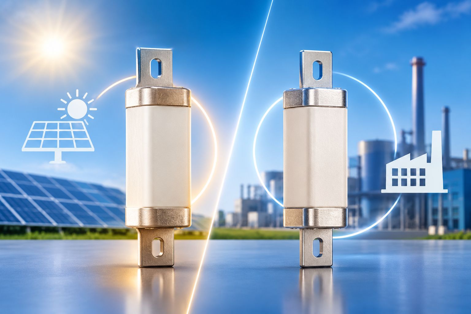
A gPV fuse is specifically engineered for photovoltaic (PV) systems and DC applications, while a gG fuse is primarily designed for general-purpose protection in industrial AC electrical systems.
Understanding the differences between gPV vs gG fuse classes helps electrical engineers, system integrators, installers, and procurement professionals select the appropriate protection device for their installations.
In this guide, we explain how gPV and gG fuses work, their technical characteristics, applications, and the important factors to consider when choosing between them.
1. What Are gPV and gG Fuse Classes?
Both gPV and gG fuses belong to the utilization categories defined under the IEC 60269 family of international fuse standards.
The letter "g" represents full-range protection. This means the fuse is designed to interrupt both overload currents and short-circuit currents within its specified operating conditions.
The second part of the designation identifies the intended application.
What Is a gPV Fuse?
A gPV fuse is a full-range fuse specifically designed for photovoltaic applications.
Solar PV systems operate using direct current (DC), which presents unique challenges for electrical protection. Unlike AC current, DC current does not naturally pass through zero during each cycle. Consequently, interrupting a DC fault current and extinguishing the resulting electrical arc can be more difficult.
gPV fuses are engineered to address these challenges through specially designed fuse elements, suitable breaking capacities, and effective arc-quenching materials.
Main characteristics of gPV fuses:
-
Designed specifically for photovoltaic DC circuits.
-
Suitable for high-voltage solar installations.
-
Provides overload and short-circuit protection.
-
Designed to interrupt DC fault currents safely.
-
Helps protect solar panels, cables, inverters, and other PV components.
-
Available in different current ratings and voltage configurations.
What Is a gG Fuse?
A gG fuse is a full-range general-purpose fuse commonly used in low-voltage electrical distribution and industrial AC installations.
It protects electrical cables, distribution equipment, transformers, and industrial machinery against overloads and short circuits.
gG fuses are designed to provide comprehensive protection across a wide range of operating currents. Their time-current characteristics also allow appropriate coordination with downstream equipment when correctly selected.
Main characteristics of gG fuses:
-
Designed for general-purpose electrical protection.
-
Commonly used in AC distribution systems.
-
Provides overload and short-circuit protection.
-
Protects cables, transformers, and industrial equipment.
-
Available in various current and voltage ratings.
-
Suitable for industrial switchgear and distribution panels.
2. gPV vs gG Fuse Classes: Key Differences
The main difference between gPV and gG fuses is their intended application and electrical operating environment.
Although both provide full-range protection, their design requirements, performance characteristics, and testing standards differ.
Here is a comparison of the two fuse classes:
| Comparison | gPV Fuse | gG Fuse |
|---|---|---|
| Full designation | Photovoltaic full-range fuse | General-purpose full-range fuse |
| Circuit type | DC | Primarily AC |
| Main application | Solar PV systems | Industrial electrical systems |
| Protection function | Overload and short-circuit protection | Overload and short-circuit protection |
| Arc interruption | Designed for DC arc interruption | Designed for AC fault interruption |
| Typical applications | Solar panels, PV combiner boxes, DC inverters | Distribution boards, transformers, cables |
| Operating environment | Photovoltaic installations | Industrial and commercial installations |
| Relevant standard | IEC 60269-6 | IEC 60269-2 |
| Voltage selection | According to PV system DC voltage | According to AC system voltage |
| Main purpose | Protect photovoltaic circuits | Protect general electrical circuits |
The comparison demonstrates that these fuse classes are not interchangeable simply because they share similar physical construction or current ratings.
The correct fuse must always match the electrical characteristics and protection requirements of the circuit.
3. Why Do gPV and gG Fuses Have Different Designs?
One of the most important factors in understanding gPV vs gG fuses is the difference between AC and DC electrical systems.
DC Circuit Protection
Photovoltaic systems generate direct current. During a short circuit, DC current does not have the natural zero-crossing points found in alternating-current systems.
This makes arc interruption particularly challenging.
When a fuse element melts, an electrical arc can develop between the separated sections of the element. If the arc is not extinguished effectively, it can damage equipment and create serious safety risks.
To address this issue, gPV fuses incorporate design features intended to interrupt DC fault currents safely.
These may include:
-
Specially designed fuse elements.
-
High-quality insulating enclosures.
-
Quartz sand or other suitable arc-quenching materials.
-
Appropriate DC voltage and breaking-capacity ratings.
These characteristics make gPV fuses suitable for the demanding operating conditions of photovoltaic installations.
AC Circuit Protection
Alternating current changes direction periodically and naturally passes through zero during each cycle.
This zero-crossing characteristic helps the fuse interrupt an electrical arc.
gG fuses are designed around the operating requirements of general-purpose AC electrical distribution systems.
Their time-current characteristics provide protection against both sustained overloads and high short-circuit currents.
They are commonly used in industrial environments where reliable protection of cables, electrical distribution equipment, and machinery is essential.
4. Applications of gPV Fuses
gPV fuses are widely used in solar power generation systems and other photovoltaic DC applications.
As solar installations increase in capacity and operating voltage, reliable DC circuit protection becomes increasingly important.
Solar PV Combiner Boxes
Combiner boxes collect the output from multiple photovoltaic strings.
A gPV fuse is installed in the appropriate circuit to protect individual PV strings against excessive reverse currents and fault conditions.
This helps prevent damage to solar modules and associated wiring.
Solar Inverter DC Inputs
Solar inverters convert DC electricity generated by photovoltaic modules into AC electricity.
The DC input circuits require suitable protection against overloads and short circuits.
gPV fuses provide protection designed specifically for photovoltaic DC operating conditions.
PV String Protection
Individual solar strings may experience abnormal current conditions due to wiring faults, damaged modules, or other electrical problems.
Correctly selected gPV fuses help isolate faulty circuits and reduce the risk of damage spreading throughout the installation.
Energy Storage Systems
Battery-based energy storage installations also require carefully coordinated DC protection.
Depending on the system design, voltage, and applicable standards, appropriately rated DC fuses can help protect battery connections, power conversion equipment, and associated circuits.
5. Applications of gG Fuses
gG fuses are widely used in industrial and commercial electrical installations.
Their full-range protection characteristics make them suitable for numerous low-voltage AC applications.
Industrial Distribution Boards
Industrial distribution panels supply electrical power to multiple circuits and machines.
gG fuses protect these circuits against overloads and short circuits, helping maintain safe and reliable electrical distribution.
Transformer Protection
Transformers are essential components in industrial power distribution networks.
Appropriately selected gG fuses can protect associated circuits against excessive current and short-circuit conditions.
Cable and Busbar Protection
Electrical cables and busbars can overheat when exposed to excessive current.
gG fuses help protect conductors by interrupting abnormal current conditions before thermal damage becomes excessive, provided the fuse is correctly coordinated with the conductor.
Motor Control Systems
Industrial motors can experience overloads and short circuits during operation.
gG fuses may be used as part of a motor protection arrangement. However, motor starting currents and overload protection requirements must be considered when selecting the complete protection system.
6. How to Choose Between gPV and gG Fuses
Selecting the correct fuse requires more than matching the rated current.
Engineers should evaluate several electrical and environmental parameters before making a decision.
1. Identify the Circuit Type
This is the first and most important selection criterion.
-
Choose a gPV fuse for photovoltaic DC applications.
-
Choose a gG fuse for general-purpose applications where its ratings and characteristics are suitable, particularly AC distribution systems.
Never assume that a fuse designed for one application is suitable for another.
2. Check the Rated Voltage
The fuse voltage rating must be equal to or higher than the maximum voltage that can occur in the protected circuit.
For photovoltaic systems, engineers must calculate the maximum possible PV string voltage, including the effect of low ambient temperatures on open-circuit voltage.
For AC installations, the fuse must be suitable for the system's rated operating voltage.
The DC or AC rating must always be verified separately.
3. Determine the Rated Current
The rated current must be selected according to the circuit's normal operating current, conductor capacity, and applicable installation standards.
For PV applications, engineers should consider:
-
Maximum expected string current.
-
PV module characteristics.
-
Potential reverse-current conditions.
-
Manufacturer recommendations.
-
Applicable photovoltaic protection requirements.
For industrial applications, the selection should consider cable ampacity, equipment operating current, overload characteristics, and coordination requirements.
4. Verify Breaking Capacity
Breaking capacity refers to the maximum prospective fault current that a fuse can safely interrupt at its specified voltage and operating conditions.
A fuse must have sufficient breaking capacity to interrupt the maximum possible short-circuit current at its installation point.
This is particularly important in high-voltage DC photovoltaic systems.
5. Consider Ambient Temperature
High ambient temperatures can affect fuse performance and current-carrying capacity.
When fuses operate in hot environments, their effective current-carrying capability may decrease.
Engineers should consult the manufacturer's derating curves and technical documentation when selecting fuses for installations exposed to elevated temperatures.
6. Check Mechanical Compatibility
The fuse must be mechanically compatible with the corresponding fuse holder or base.
Common NH fuse sizes include:
-
NH00
-
NH0
-
NH1
-
NH2
-
NH3
Selecting the correct physical size, contact arrangement, and mounting configuration helps ensure safe installation and reliable electrical connections.
7. Verify Standards and Certifications
Always check that the selected fuse complies with the standards relevant to its intended application.
Important standards include:
-
IEC 60269-1: General requirements for low-voltage fuses.
-
IEC 60269-2: Supplementary requirements for fuses used by authorized persons, particularly industrial applications.
-
IEC 60269-6: Supplementary requirements for fuse-links used for the protection of solar photovoltaic energy systems.
-
UL 248-19: Requirements for photovoltaic fuses.
Certification, test documentation, and manufacturer datasheets should be reviewed before installation.
7. Can You Use a gG Fuse Instead of a gPV Fuse?
No, a standard gG fuse should not automatically be used as a replacement for a gPV fuse in a photovoltaic DC circuit.
Although both fuse classes provide full-range protection, their electrical characteristics and intended operating conditions are different.
A gPV fuse is specifically designed and tested for photovoltaic applications, including the requirements associated with DC fault interruption.
A gG fuse may not provide the required DC voltage rating, breaking capacity, or protection characteristics for a particular PV installation.
Using an unsuitable fuse can compromise system protection and increase the risk of electrical failure.
The correct approach is to select a fuse that meets the applicable photovoltaic protection standard and the electrical requirements of the installation.
8. Common Mistakes When Selecting gPV and gG Fuses
Incorrect fuse selection can lead to equipment damage, unnecessary downtime, and electrical safety problems.
Some common mistakes include:
Selecting a fuse based only on its current rating
Two fuses with identical current ratings may have completely different voltage ratings, breaking capacities, and time-current characteristics.
Using an AC-rated fuse in a DC application
DC arc interruption requires suitable fuse construction and ratings. An AC voltage rating does not establish suitability for DC operation.
Ignoring temperature derating
High operating temperatures can affect fuse performance. Always consider installation conditions and manufacturer specifications.
Overlooking breaking capacity
The fuse must safely interrupt the maximum prospective fault current at its rated voltage.
Ignoring fuse coordination
Fuse selection should consider the entire electrical protection system, including cables, circuit breakers, inverters, and other connected equipment.
Choosing an incompatible fuse holder
Mechanical compatibility is essential for maintaining proper electrical contact and preventing excessive heating.
Avoiding these mistakes helps improve system reliability and electrical safety.
9. The Importance of Correct Fuse Selection in Modern Electrical Systems
As photovoltaic installations, industrial automation, and energy storage systems continue to develop, electrical protection requirements are becoming more demanding.
Correct fuse selection plays an important role in:
-
Preventing electrical equipment damage.
-
Reducing the risk of overheating and fire.
-
Improving system reliability.
-
Minimizing unexpected maintenance.
-
Supporting compliance with relevant electrical standards.
-
Protecting cables, inverters, and other electrical components.
For solar installations, the importance of selecting the correct gPV fuse increases as system voltages and available fault currents change.
For industrial installations, properly selected gG fuses help maintain dependable protection across electrical distribution networks.
In both cases, engineers should prioritize electrical ratings, application suitability, and verified performance rather than selecting a fuse based solely on price or physical dimensions.
10. Frequently Asked Questions About gPV vs gG Fuse Classes
Q1. What is the main difference between gPV and gG fuses?
The main difference is their intended application. gPV fuses are specifically designed for photovoltaic DC circuits, while gG fuses provide general-purpose full-range protection, commonly in industrial AC distribution systems.
Q2. What does gPV mean in a fuse?
gPV stands for a full-range photovoltaic fuse. It is designed to protect solar photovoltaic circuits against overloads and short circuits under specified DC operating conditions.
Q3. What does gG mean in fuse classification?
gG refers to a full-range general-purpose fuse. It provides protection against both overload currents and short-circuit currents in suitable electrical installations.
Q4. Are gPV fuses suitable for DC applications?
Yes. gPV fuses are specifically designed for photovoltaic DC applications and are tested according to the relevant requirements for PV fuse protection.
Q5. Can gG fuses protect solar panels?
Standard gG fuses should not be assumed suitable for photovoltaic DC circuits. Solar installations generally require appropriately rated gPV fuse-links designed and tested for PV protection.
Q6. Which standard applies to gPV fuses?
IEC 60269-6 specifies supplementary requirements for fuse-links used for the protection of solar photovoltaic energy systems.
Q7. Which standard applies to gG fuses?
IEC 60269-2 specifies supplementary requirements for low-voltage fuse-links used by authorized persons, particularly in industrial applications.
Q8. Do gPV and gG fuses provide overload and short-circuit protection?
Yes. Both are full-range fuse classes designed to provide overload and short-circuit protection within their specified operating conditions.
Q9. Are gPV fuses only used in solar power plants?
No. They can also be used in other photovoltaic DC applications, including PV combiner boxes, inverter input circuits, and suitable DC protection arrangements.
Q10. How do I select the correct fuse rating?
Consider the operating voltage, normal current, maximum prospective fault current, breaking capacity, ambient temperature, installation requirements, and applicable standards. Always follow the equipment manufacturer's recommendations and relevant electrical regulations.
Conclusion: gPV vs gG – Choosing the Right Fuse for Reliable Protection
Understanding the differences between gPV and gG fuse classes is essential for designing safe and reliable electrical systems.
While both fuse categories provide full-range overcurrent protection, they serve different purposes.
gPV fuses are designed for photovoltaic DC applications, offering protection for solar strings, combiner boxes, inverter inputs, and other PV circuits.
gG fuses are designed for general-purpose electrical protection, making them suitable for industrial distribution boards, cables, transformers, and other compatible AC installations.
The most important consideration is selecting a fuse that matches the circuit's electrical characteristics, operating conditions, and protection requirements.
By evaluating voltage ratings, current ratings, breaking capacity, temperature conditions, mechanical compatibility, and applicable standards, engineers can make informed decisions and improve the long-term safety and reliability of electrical installations.
- Details
- Category: Electrical Fuses Blog
| eaton-bussmann-series-dc-fuses-catalog-ca135009en-us.pdf | [Eaton Bussmann DC Fuses] | 0 kB |
| eaton-bussmann-series-photovoltaic-fuses-catalogue-ca135004en.pdf | [Eaton Bussmann PV Fuses] | 0 kB |
DC Fuse 1000V: Essential Guide for High-Voltage Systems
As electrical technology continues to advance, high-voltage direct current (DC) systems are becoming increasingly important across renewable energy, electric vehicles, industrial automation, and energy storage applications. These systems require reliable protection against electrical faults to maintain operational safety, prevent equipment damage, and ensure long-term performance.
One of the most important protective components in these installations is the DC Fuse 1000V.
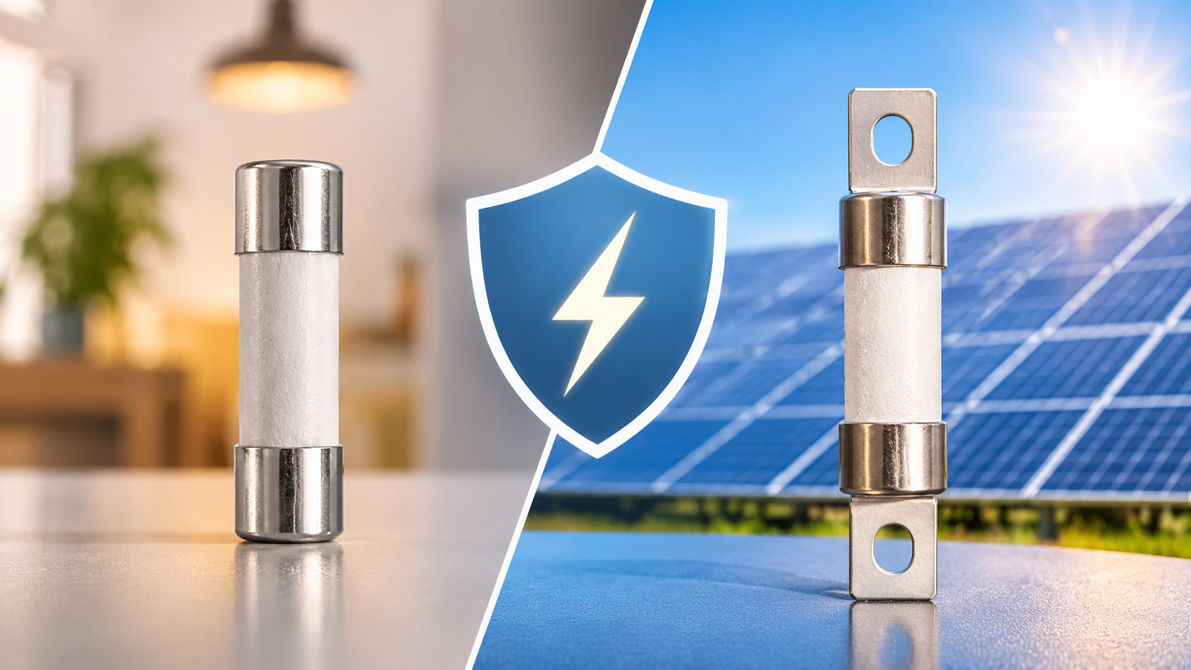
A 1000V DC fuse is specifically designed to interrupt excessive current in high-voltage DC circuits. It helps protect electrical equipment against overloads and short circuits while reducing the risk of overheating, electrical fires, and system failures.
Understanding how a 1000V DC fuse works, where it is used, and how to select the right specification is essential for engineers, electrical contractors, system integrators, and equipment manufacturers.
This guide explores the working principles, applications, key features, selection criteria, and benefits of 1000V DC fuses in modern high-voltage electrical systems.
1. What Is a DC Fuse 1000V?
A DC Fuse 1000V is an electrical protection device designed for direct current circuits with operating voltages up to 1000 volts DC, provided the fuse's specified voltage rating and application conditions are suitable.
Its primary function is to protect electrical circuits from excessive current caused by overloads or short circuits.
A typical fuse contains a specially engineered metal element that melts when the current exceeds a predetermined level for a sufficient period. Once the element melts, the electrical circuit is interrupted, preventing excessive current from damaging connected components.
Unlike AC circuits, DC circuits do not naturally experience periodic current zero crossings. This makes interrupting a DC fault particularly challenging because the electrical arc can continue after the fuse element melts.
For this reason, high-voltage DC fuses require carefully designed arc-extinguishing structures and materials.
Main Components of a 1000V DC Fuse
A high-voltage DC fuse generally consists of several important components:
1. Fusible Element
The fusible element is the central component responsible for interrupting excessive current. It is typically manufactured from specially selected conductive materials, such as silver or copper, depending on the fuse design.
2. Arc-Quenching Material
When the fusible element melts, an electrical arc may develop. Arc-quenching materials, commonly specialized silica-based fillers, help absorb energy and extinguish the arc safely.
3. Fuse Housing
The housing protects the internal components from environmental conditions, mechanical damage, and elevated operating temperatures.
4. End Caps or Terminals
These components provide electrical connections between the fuse and the protected circuit. Their construction helps maintain reliable electrical contact during operation.
Together, these components allow a 1000V DC fuse to provide dependable overcurrent protection in demanding electrical environments.
2. How Does a 1000V DC Fuse Work?
The operating principle of a 1000V DC fuse is based on the heating effect of electrical current.
Under normal operating conditions, current flows through the fusible element without causing it to melt. However, when an overload or short circuit occurs, the current increases beyond the fuse's designed operating conditions.
This excessive current generates heat within the fusible element.
When the temperature reaches the melting point of the element, it melts and creates a gap in the electrical circuit.
In high-voltage DC applications, interrupting the resulting electrical arc is especially important. The fuse's internal arc-quenching structure helps control and extinguish the arc, allowing the circuit to be safely interrupted within its rated breaking capacity.
Understanding the Fuse Protection Process
The protection process generally involves four stages:
-
Normal operation: Current flows through the fuse without interrupting the circuit.
-
Overcurrent detection: Excessive current generates additional heat in the fusible element.
-
Fuse element melting: The element melts when its operating characteristics are exceeded.
-
Arc interruption: The internal arc-quenching system helps extinguish the electrical arc and isolate the faulty circuit.
The speed of operation depends on the magnitude of the fault current and the fuse's time-current characteristics.
Selecting the correct fuse is therefore essential for achieving effective protection without unnecessary interruptions during normal operation.
3. Major Applications of 1000V DC Fuses
The demand for high-voltage DC protection continues to grow as industries adopt electrification, renewable energy, and advanced energy storage technologies.
A 1000V DC fuse is suitable for various applications where high-voltage DC circuits require dependable overcurrent protection.
3.1 Solar Photovoltaic Systems
Solar photovoltaic installations are among the most common applications for 1000V DC fuses.
Solar panels generate direct current, which is collected through strings and combined before being transferred to inverters.
Electrical faults can occur because of damaged cables, defective modules, insulation failures, or short circuits.
A properly selected photovoltaic fuse helps protect solar strings and associated equipment by interrupting excessive fault currents.
Important applications include:
-
Solar panel string protection.
-
Combiner box protection.
-
DC distribution systems.
-
Photovoltaic inverter protection.
-
Solar power generation installations.
Using appropriately rated DC fuses helps improve system safety and reduce the potential impact of electrical faults.
3.2 Electric Vehicle Charging Infrastructure
Electric vehicle charging technology increasingly relies on high-voltage DC systems to support faster charging and higher power delivery.
High-power charging equipment contains sensitive electrical components that require effective protection against overcurrent conditions.
A 1000V DC fuse can be used in suitable charging system designs to protect:
-
DC power distribution circuits.
-
Charging power modules.
-
Battery charging circuits.
-
High-voltage electrical connections.
-
Power conversion equipment.
Proper fuse coordination helps protect equipment and minimize the consequences of electrical faults.
3.3 Energy Storage Systems
Battery energy storage systems are widely used in renewable energy installations, commercial facilities, and industrial power management.
These systems store electrical energy and release it when required.
However, battery systems can deliver substantial fault currents under certain conditions. Short circuits and internal battery faults may create serious safety risks.
High-voltage DC fuses help protect battery modules, DC busbars, power conversion systems, and other electrical components.
When selecting a fuse for an energy storage system, engineers should consider battery fault-current characteristics, system voltage, thermal conditions, and required interruption capacity.
3.4 Industrial Automation
Modern industrial facilities use DC power systems for motor drives, automation equipment, control systems, and power distribution.
Electrical faults can interrupt production and damage expensive machinery.
A properly specified 1000V DC fuse helps protect critical electrical components and supports reliable industrial operation.
Typical applications include:
-
Industrial DC distribution panels.
-
Motor drive systems.
-
Power conversion equipment.
-
Manufacturing automation.
-
Industrial battery systems.
3.5 Data Centers and Backup Power Systems
Data centers depend on continuous electrical power to maintain servers, networking equipment, and critical infrastructure.
DC power distribution and battery backup systems require reliable protection against overloads and short circuits.
High-voltage DC fuses can provide protection in appropriately designed power distribution and energy storage circuits.
Their correct selection helps improve electrical safety and reduce the risk of equipment damage.
4. Key Benefits of Using a DC Fuse 1000V
Installing an appropriately rated 1000V DC fuse provides several important advantages for high-voltage electrical systems.
4.1 Reliable Overcurrent Protection
The primary advantage is protection against excessive current.
By interrupting overloads and short circuits within its specified operating characteristics, a DC fuse helps prevent damage to cables, electrical equipment, and connected components.
4.2 Improved Electrical Safety
Electrical faults can cause overheating, insulation damage, and dangerous electrical arcs.
A properly selected DC fuse helps isolate faulty circuits and reduce the potential consequences of these events.
However, it must be used as part of a comprehensive electrical protection system.
4.3 Effective DC Arc Interruption
DC circuits present specific arc-interruption challenges because the current does not naturally pass through zero.
High-voltage DC fuses incorporate specialized internal structures to control and extinguish electrical arcs during fault interruption.
This feature is particularly important in photovoltaic installations, battery storage systems, and industrial DC applications.
4.4 Reduced Equipment Damage
Electrical faults can damage expensive components, including inverters, power converters, battery systems, and industrial machinery.
An appropriately coordinated fuse helps limit the energy released during a fault, reducing the potential for extensive equipment damage.
4.5 Long-Term Operational Reliability
High-quality DC fuses are designed to operate under specified electrical and environmental conditions.
Selecting suitable products and maintaining them according to manufacturer recommendations helps support consistent protection throughout the system's service life.
5. How to Choose the Right 1000V DC Fuse
Choosing the correct DC fuse is essential for ensuring reliable protection and maintaining electrical system performance.
A fuse should never be selected based on voltage rating alone. Several electrical, mechanical, and environmental factors must be evaluated.
5.1 Voltage Rating
The fuse's rated DC voltage must be equal to or greater than the maximum voltage that can occur across it under the intended operating conditions.
For a system operating at 1000V DC, select a fuse specifically rated for the applicable DC voltage.
Remember that photovoltaic systems may experience increased open-circuit voltage at low temperatures. Engineers must calculate the maximum possible system voltage before selecting a fuse.
5.2 Current Rating
The rated current of the fuse must be appropriate for the normal operating current and the characteristics of the protected circuit.
An undersized fuse may operate unnecessarily during normal conditions.
An oversized fuse may fail to provide adequate protection to cables and connected equipment.
Fuse sizing should account for:
-
Continuous operating current.
-
Expected load variations.
-
Ambient temperature.
-
Installation conditions.
-
Cable ampacity.
-
Applicable electrical standards.
5.3 Breaking Capacity
Breaking capacity, also known as interrupting capacity, indicates the maximum prospective fault current that a fuse can safely interrupt under specified conditions.
This is one of the most important factors when selecting a high-voltage DC fuse.
The fuse's rated breaking capacity must be sufficient for the maximum prospective short-circuit current at its installation location.
For battery systems and high-power DC applications, fault current can be particularly significant.
5.4 Time-Current Characteristics
Time-current characteristics describe how quickly a fuse operates at different current levels.
Engineers should examine these characteristics to ensure that the fuse provides suitable protection against both overloads and short circuits.
Proper coordination with upstream and downstream protective devices is also important.
5.5 Environmental Conditions
Operating environments can influence fuse performance and service life.
Consider the following factors:
-
Ambient operating temperature.
-
Humidity and moisture.
-
Dust and contamination.
-
Mechanical vibration.
-
Installation ventilation.
-
Corrosive environmental conditions.
For outdoor solar installations and industrial environments, selecting a fuse with suitable environmental and thermal characteristics is especially important.
5.6 Fuse Size and Mounting Compatibility
The physical dimensions and installation configuration must match the intended fuse holder or mounting arrangement.
Common fuse formats include cylindrical cartridge designs and industrial blade-type fuse links.
Always verify the following:
-
Fuse dimensions.
-
Terminal configuration.
-
Mounting requirements.
-
Compatible fuse holder.
-
Electrical connection specifications.
Mechanical compatibility is essential for maintaining reliable electrical contact and preventing overheating.
5.7 Certifications and Compliance
Always check the applicable product standards and certification requirements before purchasing a 1000V DC fuse.
Relevant standards may include:
-
IEC 60269: Low-voltage fuses.
-
UL 248: Low-voltage fuses, including applicable DC fuse requirements.
The exact standard and certification requirements depend on the fuse category, application, and target market.
6. Common Types of 1000V DC Fuses
Different electrical installations require different fuse designs.
Understanding the available types can help engineers identify the most suitable protection solution.
6.1 Cylindrical DC Fuses
Cylindrical fuses are commonly used in photovoltaic systems and DC distribution applications.
They are available in different dimensions and current ratings.
Their compact design makes them suitable for installation in compatible fuse holders and combiner boxes.
6.2 NH-Type DC Fuses
NH-type fuses are commonly used in industrial power distribution and higher-current applications.
They feature a robust construction and are available in different sizes and electrical ratings.
When used in DC systems, the specific fuse must have an appropriate DC voltage and breaking-capacity rating.
6.3 High-Current DC Fuses
High-current DC fuses are designed for applications requiring higher current-carrying capabilities.
They may be used in energy storage systems, industrial DC distribution, and specialized power equipment.
Selection should consider the expected continuous current, fault-current level, connection design, and thermal performance.
7. DC Fuse 1000V vs. AC Fuse: What Is the Difference?
Although both AC and DC fuses provide overcurrent protection, their electrical operating conditions are different.
Understanding these differences is important when selecting protective devices.
| Comparison Factor | DC Fuse 1000V | AC Fuse |
|---|---|---|
| Current Type | Direct current | Alternating current |
| Current Direction | Generally unidirectional | Alternates periodically |
| Current Zero Crossing | No natural periodic zero crossing | Natural zero crossings |
| Arc Interruption | Requires suitable DC arc-extinguishing design | Uses AC-rated interruption design |
| Typical Applications | Solar PV, batteries, EV systems | AC distribution, motors, industrial equipment |
| Voltage Rating | Must have an appropriate DC rating | Must have an appropriate AC rating |
One important consideration is that an AC voltage rating cannot automatically be applied to a DC circuit.
The fuse must be specifically suitable for the intended DC voltage and prospective fault current.
Using an incorrectly rated fuse can create serious electrical safety risks.
8. Installation and Maintenance Best Practices
Correct installation is just as important as selecting the appropriate fuse.
Even a high-quality DC fuse may not provide reliable protection if it is installed incorrectly or used outside its rated operating conditions.
Follow these important practices:
1. Verify Electrical Ratings
Before installation, check the fuse's voltage rating, current rating, breaking capacity, and application category.
2. Use Compatible Fuse Holders
Ensure that the fuse holder is designed for the selected fuse and is suitable for the system's operating voltage and current.
3. Follow Manufacturer Instructions
Install the fuse according to the specified mounting and connection requirements.
4. Inspect Electrical Connections
Loose or improperly installed connections can generate excessive heat and increase electrical resistance.
5. Monitor Operating Temperature
Unusual temperature increases around fuse connections may indicate poor contact, excessive loading, or other electrical problems.
6. Replace Operated Fuses Correctly
Always investigate the underlying fault before replacing a blown fuse.
Never replace a fuse with one having a higher current rating simply to prevent repeated operation.
7. Follow Electrical Safety Procedures
High-voltage DC systems can remain dangerous even after normal power sources are disconnected.
Installation, inspection, and replacement should be performed by qualified personnel using appropriate isolation and verification procedures.
9. Common Mistakes to Avoid When Selecting a 1000V DC Fuse
Incorrect fuse selection can compromise the safety and reliability of an electrical installation.
Some common mistakes include:
-
Ignoring DC voltage ratings: Selecting a fuse based only on its current rating without checking its DC voltage capability.
-
Underestimating fault current: Choosing a fuse with insufficient breaking capacity.
-
Incorrect current sizing: Selecting a fuse that does not adequately protect the connected cables and equipment.
-
Ignoring temperature effects: Failing to consider ambient temperature and installation conditions.
-
Using incompatible fuse holders: Installing a fuse in a holder that does not meet the required electrical specifications.
-
Ignoring coordination: Failing to coordinate protective devices across the electrical system.
-
Replacing fuses without investigating faults: Installing a replacement without identifying why the original fuse operated.
Avoiding these mistakes helps ensure that the protection system operates as intended.
10. Frequently Asked Questions About DC Fuse 1000V
Q1. What is a 1000V DC fuse used for?
A 1000V DC fuse protects high-voltage direct current circuits against excessive current caused by overloads and short circuits.
It is commonly used in solar photovoltaic systems, battery energy storage installations, electric vehicle charging equipment, and industrial DC power distribution.
Q2. Can I use an AC fuse in a 1000V DC system?
Not unless the fuse manufacturer explicitly specifies that the particular fuse is suitable for the intended DC application.
AC and DC circuits have different arc-interruption characteristics. Always verify the DC voltage rating and breaking capacity before installation.
Q3. How do I select the correct current rating for a 1000V DC fuse?
Start by determining the normal operating current and maximum expected load.
Then consider cable ampacity, ambient temperature, overload characteristics, fault-current requirements, and applicable electrical standards.
The selected fuse must provide suitable protection without unnecessary operation during normal system conditions.
Q4. What is the breaking capacity of a DC fuse?
Breaking capacity is the maximum prospective fault current that a fuse can safely interrupt under its specified operating conditions.
The fuse's breaking capacity must be equal to or greater than the maximum prospective short-circuit current at the installation point.
Q5. Are 1000V DC fuses suitable for solar power systems?
Yes. Appropriately rated 1000V DC photovoltaic fuses are commonly used to protect solar panel strings, combiner boxes, and other DC circuits.
The fuse must meet the system's maximum voltage, current, and fault-interruption requirements.
Q6. How often should a 1000V DC fuse be replaced?
A DC fuse does not normally require replacement simply because a certain period has passed.
Replacement is generally necessary after the fuse operates or when inspection identifies damage, deterioration, or other conditions requiring replacement.
Always follow the manufacturer's maintenance recommendations.
Q7. What happens if I use an oversized DC fuse?
An oversized fuse may not provide adequate protection to the connected cables and electrical equipment.
It can allow excessive current to flow for longer than the protected components can safely withstand, increasing the risk of overheating and equipment damage.
Q8. Can 1000V DC fuses be connected in parallel?
Parallel fuse configurations require careful engineering.
Unequal current sharing, differences in resistance, and thermal variations can cause individual fuses to operate differently.
Such configurations should only be used when specifically designed, evaluated, and approved for the application.
11. Conclusion: Why 1000V DC Fuse Protection Matters
As high-voltage DC technology continues to expand across renewable energy, electric mobility, industrial automation, and energy storage, reliable circuit protection is becoming increasingly important.
A DC Fuse 1000V plays a vital role in protecting electrical equipment against overloads and short circuits. Its specialized construction and arc-extinguishing capabilities make it suitable for demanding DC applications when correctly selected and installed.
However, choosing the right fuse requires more than simply matching the voltage rating. Engineers must evaluate current requirements, breaking capacity, time-current characteristics, environmental conditions, mounting compatibility, and applicable safety standards.
By considering these factors, businesses and electrical professionals can build safer, more reliable, and more efficient high-voltage DC systems.
Ultimately, investing in properly specified DC fuse protection helps reduce electrical risks, protect valuable equipment, and support the long-term performance of modern power installations.
- Details
- Category: Electrical Fuses Blog
| eaton-bussmann-series-photovoltaic-fuses-catalogue-ca135004en.pdf | [Eaton Bussmann PV Fuses] | 0 kB |
How Do Photovoltaic Fuses Work With Other Protection Components in a Solar System?
Introduction
Solar energy systems rely on several electrical components working together to generate, convert, and distribute electricity safely and efficiently. While solar panels and inverters receive much of the attention, electrical protection components play an equally important role in ensuring system reliability, preventing equipment damage, and reducing potential fire hazards.
Among these components, photovoltaic (PV) fuses are essential for protecting solar installations against overcurrent conditions, short circuits, and reverse current faults. However, a photovoltaic fuse does not operate independently. It works alongside other protection devices, including circuit breakers, surge protection devices (SPDs), DC isolator switches, and grounding systems.
Each protection component performs a specific function, and their coordinated operation creates a comprehensive electrical safety system.
Understanding how photovoltaic fuses work with other protection components helps solar installers, electrical engineers, system designers, and solar energy professionals make better decisions when designing and maintaining photovoltaic installations.
This article explores the role of PV fuses, their interaction with other solar protection components, and why proper coordination is essential for long-term system performance.
1. What Are Photovoltaic Fuses and Why Are They Important?
Photovoltaic fuses are specialised electrical protection devices designed specifically for the direct current (DC) characteristics of solar power systems.
Unlike conventional electrical fuses, PV fuses are engineered to operate under the unique conditions of photovoltaic installations, including high DC voltages, continuous current generation, and potentially persistent electrical arcs.
Their primary function is to interrupt excessive current when an electrical fault occurs.
In a typical solar installation, multiple solar panels are connected in series to form strings. Several strings may then be connected in parallel to increase the overall current output.
When one string experiences a short circuit or another electrical fault, current from the healthy parallel strings may flow back into the damaged string. This reverse current can exceed the safe operating limits of solar modules, cables, and connectors.
A properly selected photovoltaic fuse detects this excessive current and interrupts the affected circuit before significant damage occurs.
Key Functions of Photovoltaic Fuses
PV fuses provide several important protective functions:
-
Overcurrent protection: Interrupt excessive current before cables and electrical components overheat.
-
Short-circuit protection: Disconnect faulty circuits when dangerous short-circuit currents occur.
-
Reverse current protection: Prevent excessive backfeed current from healthy parallel strings into a faulted string.
-
Equipment protection: Help protect solar modules, wiring, connectors, and other electrical components.
-
Fire prevention: Reduce the risk of overheating and electrical fires caused by sustained fault currents.
Photovoltaic fuses are commonly installed in string combiner boxes, DC distribution enclosures, and other designated protection points.
For reliable operation, they must be specifically rated for photovoltaic applications and selected according to the system's maximum DC voltage, operating current, and expected fault conditions.
2. How Do PV Fuses Work With Solar Circuit Breakers?
Circuit breakers and photovoltaic fuses are both overcurrent protection devices. However, they operate differently and often serve different purposes within a solar installation.
A PV fuse contains a calibrated metal element that melts when excessive current flows through it for a sufficient period. Once the element melts, the electrical circuit is interrupted.
A circuit breaker, on the other hand, uses a mechanical switching mechanism to disconnect a circuit when an overcurrent or short-circuit condition is detected.
Depending on its design, a circuit breaker may use thermal and magnetic tripping mechanisms.
How They Work Together
In a solar power system, photovoltaic fuses typically provide individual string-level protection, while circuit breakers can protect larger distribution circuits and downstream electrical equipment.
For example:
-
PV fuses protect individual solar strings against excessive reverse current.
-
DC circuit breakers provide overcurrent protection for designated DC distribution circuits.
-
AC circuit breakers protect inverter output circuits and downstream AC distribution systems.
This arrangement creates multiple layers of protection throughout the installation.
If an individual solar string develops a fault, its associated fuse can disconnect that string without necessarily interrupting the operation of the entire solar array.
Meanwhile, a correctly selected upstream circuit breaker provides additional protection for the larger circuit it serves.
Why Proper Coordination Matters
The relationship between PV fuses and circuit breakers is particularly important when designing a selective protection system.
Protection coordination, also known as selectivity or discrimination, aims to ensure that the protective device closest to a fault operates first whenever the system design and available fault current permit.
Without proper coordination, an upstream protective device may trip unnecessarily, disconnecting a larger portion of the solar installation.
This can increase system downtime and reduce energy production.
Therefore, fuse ratings, circuit breaker characteristics, interrupting capacities, and conductor specifications must be evaluated together.
3. How Do Photovoltaic Fuses Work With Surge Protection Devices?
Surge protection devices (SPDs) provide another essential layer of protection in photovoltaic installations.
While PV fuses primarily protect against excessive current, surge protection devices are designed to protect electrical equipment against transient overvoltages.
These voltage surges may result from:
-
Nearby or direct lightning activity.
-
Switching operations in electrical networks.
-
Sudden voltage disturbances.
-
Electromagnetic interference associated with lightning events.
Excessive transient voltage can damage sensitive solar equipment, including inverters, monitoring systems, and other electronic components.
Understanding the Different Protection Functions
PV fuses and surge protection devices address different electrical risks.
A photovoltaic fuse responds to excessive current by interrupting the circuit.
An SPD responds to transient overvoltage by temporarily providing a low-impedance path for surge current, diverting it away from sensitive equipment toward the appropriate protective earthing system.
Once the surge has passed, the SPD returns to its normal operating condition if it has not reached the end of its service life or failed.
How They Work Together
In a typical photovoltaic installation, DC surge protection devices are installed at appropriate points between the solar array and inverter.
The SPD limits transient overvoltages, while PV fuses provide overcurrent protection for the relevant DC circuits.
Some surge protection devices also incorporate or require dedicated backup overcurrent protection.
In such cases, the backup fuse or circuit breaker must be selected according to the SPD manufacturer's specifications and the installation's electrical characteristics.
This coordination is important because an SPD can experience a failure condition that results in a sustained short circuit.
The associated protective device must be capable of safely disconnecting the failed SPD under the specified conditions.
Important: Standard PV string fuses should not automatically be considered substitutes for the dedicated backup protection required by a surge protection device.
Both components must be selected according to their intended functions.
4. How Do PV Fuses Work With DC Isolator Switches?
DC isolator switches are essential safety components in photovoltaic installations.
Their primary purpose is to provide a means of disconnecting electrical circuits during maintenance, inspection, troubleshooting, or emergency procedures.
Solar panels continue generating electricity whenever they receive sufficient sunlight. Consequently, disconnecting the AC supply does not automatically eliminate the DC voltage generated by the solar array.
A properly rated DC isolator allows authorised personnel to separate designated sections of the solar installation safely.
Differences Between PV Fuses and DC Isolators
Although both components can interrupt electrical circuits, their functions are different.
Photovoltaic fuses:
-
Automatically interrupt circuits when excessive current occurs.
-
Protect against specified overcurrent and short-circuit conditions.
-
Operate without manual intervention.
-
Must be replaced after operation.
DC isolator switches:
-
Provide manual electrical disconnection.
-
Allow designated circuits to be isolated for maintenance.
-
Can be operated by authorised personnel.
-
Must have suitable DC voltage, current, and load-breaking ratings for their intended application.
How They Complement Each Other
Consider a solar installation with several parallel PV strings.
Individual string fuses protect the strings against excessive reverse current. A DC isolator provides a means of disconnecting the relevant section of the array from the inverter.
If a string develops an electrical fault, its fuse can interrupt the faulty circuit automatically.
If maintenance is subsequently required, the appropriate DC isolator can be operated according to the system's safe isolation procedure.
Together, these components provide automatic fault protection and controlled electrical disconnection.
It is important to understand that a DC isolator is not necessarily an overcurrent protection device. It should not replace a properly rated photovoltaic fuse or DC circuit breaker.
5. How Do Photovoltaic Fuses Work With Grounding and Earthing Systems?
Grounding, also known as earthing, is another important element of solar electrical protection.
Its purpose is to provide an appropriate protective connection for exposed conductive parts and help control dangerous touch voltages under fault conditions.
In photovoltaic installations, grounding and bonding arrangements may include:
-
Solar panel frames.
-
Mounting structures.
-
Inverter enclosures.
-
Metallic cable enclosures.
-
Electrical distribution equipment.
These conductive parts are connected to the protective earthing system as required by the applicable electrical installation standards.
The Relationship Between PV Fuses and Grounding
PV fuses and grounding systems perform complementary functions.
Grounding provides a protective electrical path under specified fault conditions, while fuses interrupt excessive current when the circuit conditions cause them to operate.
For example, if insulation damage causes an electrical conductor to contact an exposed metallic enclosure, the grounding system helps establish a fault-current path.
Depending on the system configuration and fault characteristics, an appropriate protective device may then disconnect the affected circuit.
However, not every ground fault will produce enough current to operate a conventional fuse. This is particularly important in certain ungrounded or high-resistance photovoltaic systems.
Therefore, grounding must be combined with appropriate fault detection, insulation monitoring, and overcurrent protection where required.
Grounded and Ungrounded PV Systems
The arrangement of photovoltaic fuses depends partly on the grounding configuration.
In certain grounded systems, overcurrent protection is generally applied to ungrounded conductors, subject to applicable exceptions and installation requirements.
In ungrounded systems, both DC conductors may require overcurrent protection.
The correct arrangement must be determined according to the system design and relevant electrical standards.
6. How Do PV Fuses Work With Solar Inverters?
Solar inverters convert the DC electricity generated by photovoltaic modules into alternating current (AC) for use in buildings or connection to the electrical grid.
As one of the most important components in a solar power system, the inverter requires suitable protection on both its DC input and AC output sides.
DC-Side Protection
On the DC side, photovoltaic fuses protect designated string circuits against excessive current.
Additional protective components may include:
-
DC circuit breakers.
-
DC isolator switches.
-
DC surge protection devices.
-
Insulation monitoring and fault detection systems.
These components help protect the electrical connection between the solar array and inverter.
AC-Side Protection
After the inverter converts DC electricity into AC electricity, a different set of protective devices is used.
These may include:
-
AC circuit breakers.
-
Residual current devices (RCDs), where required.
-
AC surge protection devices.
-
Protective earthing and bonding systems.
Each device addresses a specific electrical hazard.
For example, AC circuit breakers provide overcurrent protection for the relevant AC circuits, while appropriately selected RCDs provide additional protection against residual currents.
AC surge protection devices help protect equipment against transient overvoltages on the AC network.
Why DC and AC Protection Must Be Coordinated
DC and AC electrical circuits have different operating characteristics.
DC current does not naturally pass through zero as AC current does. Consequently, interrupting a DC fault current can be more challenging because electrical arcs may persist.
For this reason, photovoltaic fuses, DC circuit breakers, and DC isolators must have ratings specifically suitable for their intended DC applications.
Using an AC-rated protective device in a DC circuit without an appropriate DC rating can create serious safety risks.
7. The Role of PV Fuses in Solar Combiner Boxes
A solar combiner box is an electrical enclosure that brings together multiple photovoltaic string circuits before connecting them to downstream equipment.
It is one of the most common locations for photovoltaic overcurrent protection.
In larger solar installations, several strings are connected in parallel. Their combined output is then directed toward an inverter or another distribution stage.
Why Are PV Fuses Installed in Combiner Boxes?
When multiple strings operate in parallel, healthy strings can contribute reverse current to a faulty string.
This current may exceed the maximum current that the damaged string or its components can safely withstand.
String fuses help prevent this condition by disconnecting the affected circuit when the specified overcurrent threshold and operating time are reached.
A typical solar combiner box may contain:
-
PV string fuses and fuse holders.
-
DC surge protection devices.
-
DC disconnect switches.
-
Output terminals and distribution connections.
-
Monitoring or measurement equipment.
The exact configuration depends on the system's size, design, and protection requirements.
How Multiple Protection Components Work Together
Consider a solar installation containing several parallel photovoltaic strings.
Each string has an appropriately rated fuse.
The strings connect to a combiner box, where their electrical outputs are combined.
A surge protection device helps limit transient overvoltages, while an appropriately rated DC isolator provides a means of disconnecting the combined circuit.
A downstream DC circuit breaker or other protective device may provide additional protection for the output circuit, depending on the installation design.
If one string develops a fault, its fuse can isolate the affected circuit while the remaining strings continue operating, provided no other protection or control condition requires a wider shutdown.
This arrangement improves fault containment and can reduce unnecessary system interruptions.
8. Why Is Proper Coordination Between Solar Protection Components Important?
A reliable photovoltaic installation requires more than simply installing individual protective devices.
Each component must be selected and coordinated according to the electrical characteristics of the system.
Poor coordination can result in inadequate fault protection, unnecessary disconnections, equipment damage, and potential safety hazards.
Several factors must be considered during system design.
1. Correct Voltage Ratings
PV fuses, circuit breakers, isolators, and surge protection devices must have suitable voltage ratings.
The maximum possible PV array voltage must be calculated by considering the modules' open-circuit voltage and the effect of the lowest expected operating temperature.
The protective device must be suitable for the resulting maximum system voltage.
2. Correct Current Ratings
Fuse selection must account for the maximum expected PV circuit current, applicable design factors, and the maximum series fuse rating specified for the modules.
An undersized fuse may operate unnecessarily during normal conditions.
An oversized fuse may fail to provide adequate protection.
3. Breaking Capacity
The breaking capacity of a fuse or circuit breaker must be sufficient to interrupt the maximum prospective fault current under the specified operating conditions.
This is particularly important in DC photovoltaic systems, where electrical arcs can be difficult to extinguish.
4. Selective Coordination
Protective devices should be coordinated so that the device closest to the fault operates first whenever practicable.
This helps minimise unnecessary shutdowns and improves system availability.
5. Environmental Conditions
Solar installations are frequently exposed to high temperatures, humidity, dust, vibration, and changing weather conditions.
Protection components must be suitable for their installation environment.
Fuse holders and enclosures should also provide appropriate protection against environmental exposure.
6. Compliance With Applicable Standards
PV protection components must meet the relevant electrical safety and performance standards.
Depending on the installation and jurisdiction, important standards may include:
-
IEC 60269-6 for fuse-links used in photovoltaic energy systems.
-
IEC 62548-1 for photovoltaic array design requirements.
-
IEC 61643-31 for surge protective devices used on the DC side of photovoltaic installations.
-
IEC 60364 for low-voltage electrical installations.
Compliance should always be assessed against the latest applicable editions and national requirements.
9. Common Mistakes When Selecting and Installing PV Protection Components
Even high-quality protection components may fail to provide adequate protection if they are incorrectly selected or installed.
Some common mistakes include:
Using conventional fuses instead of PV-rated fuses
Photovoltaic circuits have specific DC voltage and current characteristics. Conventional fuses may not provide the required performance under PV operating conditions.
Selecting incorrect fuse ratings
Fuse ratings must be coordinated with module specifications, string current, cable ampacity, and maximum system voltage.
Ignoring reverse current protection
In parallel-connected solar strings, reverse current can damage modules and associated wiring if appropriate protection is not provided.
Using AC-rated devices in DC circuits
AC and DC circuits have different interruption characteristics. Protective devices must be rated for their intended application.
Ignoring SPD backup protection requirements
Surge protection devices may require dedicated backup overcurrent protection. Failing to provide the specified protection can compromise system safety.
Neglecting regular inspections
Loose connections, damaged insulation, corrosion, overheating, and deteriorated protective devices can reduce the effectiveness of the entire protection system.
Regular inspection and maintenance help identify potential problems before they develop into serious electrical faults.
10. Best Practices for Designing a Reliable Solar Protection System
A properly designed solar protection system should provide coordinated protection throughout the entire electrical installation.
The following practices can help improve overall safety and reliability:
-
Calculate system voltage and current accurately: Consider the maximum PV open-circuit voltage, short-circuit current, temperature variations, and number of parallel strings.
-
Use dedicated photovoltaic fuses: Select fuse-links designed for PV applications and suitable for the system's DC voltage and current requirements.
-
Install appropriate surge protection: Evaluate lightning exposure, cable lengths, installation characteristics, and equipment requirements when selecting DC and AC SPDs.
-
Provide suitable DC isolation: Ensure that designated PV circuits can be safely disconnected for maintenance and emergency procedures.
-
Coordinate circuit breakers and fuses: Check operating characteristics, breaking capacities, and selectivity between protective devices.
-
Implement proper grounding and bonding: Ensure exposed conductive parts are connected according to the applicable electrical installation requirements.
-
Follow manufacturer specifications: Observe installation instructions, operating limits, and backup protection requirements for every component.
-
Schedule regular maintenance: Inspect fuses, holders, electrical connections, enclosures, and other protection components for signs of deterioration or damage.
These practices help create a comprehensive protection strategy that supports safe operation and long-term solar system performance.
Conclusion
Photovoltaic fuses play a critical role in protecting solar power systems against overcurrent conditions, short circuits, and reverse current faults. However, their effectiveness depends on how well they work alongside other electrical protection components.
Circuit breakers provide additional overcurrent protection, surge protection devices help control transient overvoltages, DC isolators enable safe disconnection, and grounding systems help manage electrical fault conditions.
Solar inverters also require coordinated protection on both their DC input and AC output sides.
When these components are correctly selected, rated, and installed, they create multiple layers of electrical protection that help prevent equipment damage, improve system reliability, and reduce safety risks.
Ultimately, photovoltaic system protection should be approached as an integrated engineering process rather than a collection of independent devices. Proper coordination between PV fuses and other protection components is essential for building a safe, efficient, and dependable solar energy installation.
Frequently Asked Questions (FAQs)
1. What is the main function of a photovoltaic fuse in a solar system?
The primary function of a photovoltaic fuse is to protect designated DC circuits against excessive current. It interrupts the circuit when current exceeds its specified operating characteristics, helping prevent damage to solar modules, cables, and other electrical components.
2. Do solar panels need fuses?
Not every photovoltaic installation requires individual string fuses. Their necessity depends on the number of parallel strings, potential reverse current, module specifications, conductor ratings, and applicable electrical standards. Multiple parallel strings commonly require string-level overcurrent protection.
3. What is the difference between a PV fuse and a DC circuit breaker?
A PV fuse uses a metal element that melts when excessive current flows through it. A DC circuit breaker uses a mechanical switching mechanism to interrupt an overcurrent condition. Fuses must generally be replaced after operation, whereas suitable circuit breakers can normally be reset after the fault has been investigated and resolved.
4. Can a photovoltaic fuse protect against lightning?
A PV fuse is not designed to provide primary lightning or transient overvoltage protection. Surge protection devices are specifically designed to limit transient overvoltages and divert surge currents away from sensitive equipment.
5. Why are PV fuses installed in solar combiner boxes?
PV fuses are commonly installed in combiner boxes to protect individual parallel-connected strings. They help prevent excessive reverse current from healthy strings flowing into a faulty string.
6. Do PV fuses work with surge protection devices?
Yes. PV fuses and surge protection devices provide complementary protection. Fuses protect against overcurrent, while SPDs limit transient overvoltages. Depending on the SPD design, dedicated backup overcurrent protection may also be necessary.
7. What standards apply to photovoltaic fuses?
IEC 60269-6 is an important international standard covering fuse-links for photovoltaic energy systems. Fuse selection and installation must also comply with applicable PV system design requirements and local electrical regulations.
8. How often should solar protection components be inspected?
Inspection frequency depends on the installation environment, system design, operating conditions, and applicable maintenance requirements. Periodic professional inspections should check fuse holders, connections, isolators, surge protection devices, grounding connections, and other electrical components for damage or deterioration.
- Details
- Category: Electrical Fuses Blog
| eaton-bussmann-series-photovoltaic-fuses-catalogue-ca135004en.pdf | [Eaton Bussmann PV Fuses] | 0 kB |
How to Check Whether Photovoltaic Fuses Are Abnormal? 7 Warning Signs You Should Know
Photovoltaic (PV) fuses are essential safety components in solar power systems. They protect solar panels, electrical circuits, inverters, and other equipment against overcurrent, short circuits, and potential electrical damage. However, like other electrical components, photovoltaic fuses can deteriorate or develop faults over time.
An abnormal photovoltaic fuse may affect solar power generation, reduce system efficiency, or even create serious safety risks. Therefore, regular inspection and maintenance are essential to ensure the reliable operation of a solar PV system.
But how can you determine whether a photovoltaic fuse is abnormal? What warning signs should you look for, and how can you check its operating condition?
In this article, we explain seven important signs of photovoltaic fuse abnormalities and provide practical inspection methods to help identify potential problems before they develop into major failures.
1. Check the Photovoltaic Fuse for Physical Damage
Visual inspection is one of the simplest ways to identify an abnormal photovoltaic fuse.
During routine maintenance, carefully examine the fuse body, metal contacts, and surrounding fuse holder. A healthy fuse should have an intact housing and clean, undamaged electrical connections.
Pay particular attention to the following warning signs:
-
Cracks or fractures in the fuse housing.
-
Broken or deformed insulating components.
-
Corrosion or oxidation on metal terminals.
-
Discolouration or deformation of the fuse body.
-
Loose or damaged protective covers.
-
Signs of moisture, dust, or foreign material entering the fuse assembly.
Physical damage can compromise the insulation and electrical performance of a photovoltaic fuse. Moisture and corrosion may also increase contact resistance, potentially causing overheating or electrical failure.
If any visible damage is discovered, the affected component should be assessed by a qualified technician and replaced if necessary.
2. Check for Abnormal Temperature and Overheating
Temperature is another important indicator of photovoltaic fuse performance.
Under normal operating conditions, a properly selected and installed PV fuse should operate within its specified temperature limits. Unusually high temperatures around the fuse or fuse holder may indicate an electrical problem.
Common causes of abnormal heating include:
-
Loose electrical connections.
-
Poor contact between the fuse and fuse holder.
-
Excessive operating current.
-
Incorrect fuse specifications.
-
Oxidation or corrosion of contact surfaces.
-
Inadequate heat dissipation.
Overheating can accelerate material ageing, damage insulation, and increase the risk of electrical failure.
During maintenance, technicians can use appropriate infrared temperature measurement equipment or thermal imaging instruments to identify abnormal temperature differences between similar components operating under comparable conditions.
If a photovoltaic fuse or its holder shows abnormal heating, investigate the underlying cause rather than simply replacing the fuse.
Important: Never touch an operating fuse or electrical connection to determine its temperature. Use suitable non-contact measurement equipment.
3. Inspect the Fuse Connections for Looseness
Loose electrical connections are a common cause of overheating and premature photovoltaic fuse failure.
Solar power systems are exposed to daily temperature fluctuations, vibration, and environmental conditions. Over time, these factors may affect the mechanical stability of electrical connections.
A loose connection can increase contact resistance, resulting in excessive heat generation.
The following conditions may indicate a connection problem:
-
The fuse is not securely seated in its holder.
-
Terminal connections show signs of movement.
-
Contact surfaces are oxidised or corroded.
-
The fuse holder shows signs of heat damage.
-
Electrical connections have visible deformation.
A qualified technician should inspect the connection condition after following the appropriate system isolation procedures.
If tightening is required, use the specified torque values and suitable tools. Excessive tightening should be avoided because it may damage the fuse terminals or holder.
Regular connection inspections help maintain stable electrical contact and reduce the risk of unexpected photovoltaic fuse failures.
4. Look for Signs of Overload and Electrical Arcing
Overcurrent and electrical arcing are two important causes of photovoltaic fuse abnormalities.
A photovoltaic fuse is designed to interrupt excessive current when an electrical fault occurs. However, repeated overloads, short circuits, or poor connections can also cause visible damage to the fuse and surrounding components.
Look for the following warning signs:
-
Black or darkened areas on the fuse body.
-
Burn marks around electrical terminals.
-
Melted or deformed insulating materials.
-
Discolouration of metal contacts.
-
Evidence of electrical sparks or arcing.
-
Damaged or melted fuse holders.
These signs may indicate excessive electrical stress or an abnormal connection.
It is important to identify the original cause before installing a replacement fuse. Possible problems include damaged solar modules, defective cables, short circuits, incorrect fuse selection, or loose connections.
Simply replacing a damaged fuse without investigating the underlying fault may result in another failure.
5. Test Photovoltaic Fuse Continuity with a Multimeter
Visual inspection alone cannot always determine whether a photovoltaic fuse is functioning correctly.
A continuity test using a suitable digital multimeter is a more reliable method of checking whether the fuse element is intact.
A typical inspection procedure includes:
Step 1: Isolate the PV System
Follow the manufacturer's shutdown and isolation procedures. Apply appropriate lockout/tagout measures to prevent accidental reconnection.
Remember that solar modules can continue generating DC voltage whenever exposed to light. Switching off the inverter does not necessarily make the entire PV circuit safe.
Step 2: Verify the Absence of Voltage and Current
A qualified technician should use appropriately rated test equipment to verify the electrical condition of the circuit before accessing the fuse.
Never remove or test a photovoltaic fuse while it is energised.
Step 3: Remove the Fuse Safely
Once the circuit has been verified as safe, remove the fuse using an appropriate fuse extraction tool.
Testing the fuse outside its holder helps prevent parallel electrical paths from affecting the measurement.
Step 4: Set the Multimeter to Continuity Mode
Select the continuity testing function on the digital multimeter.
Place one test probe against each metal terminal of the fuse.
Step 5: Interpret the Measurement
The results generally indicate the following:
-
Continuous beep: The fuse element is electrically continuous.
-
No beep or open-circuit reading: The fuse element may have blown.
-
Unstable or unusually high resistance: Further inspection is necessary to determine whether the fuse or testing equipment is faulty.
A healthy fuse should generally have very low electrical resistance.
Always consider the multimeter manufacturer's instructions and the specific fuse design when interpreting measurements.
6. Check Whether the Fuse Is Operating Within Its Rated Specifications
Incorrect fuse selection can cause serious problems in photovoltaic systems.
A fuse may appear physically normal but still be unsuitable for the electrical circuit in which it is installed.
Several important specifications should be checked:
Rated Voltage
The fuse's rated DC voltage must be suitable for the maximum possible system voltage. Photovoltaic systems may operate at high DC voltages, making correct voltage selection particularly important.
Rated Current
The rated current must be appropriate for the circuit's operating conditions and the applicable PV system design requirements.
An incorrectly selected current rating may result in nuisance operation or inadequate protection.
Breaking Capacity
The fuse must have sufficient DC breaking capacity to safely interrupt the prospective fault current under the specified operating conditions.
Fuse Type and Application
Photovoltaic circuits require appropriately designed DC-rated protective devices. An unsuitable fuse may not safely interrupt the electrical current generated during a fault.
Physical Dimensions and Compatibility
The fuse dimensions, terminal design, and holder compatibility should match the installed electrical equipment.
Always compare the fuse specifications with the system design documentation and equipment requirements. Never assume that the rating of an existing fuse is correct simply because it was previously installed.
7. Monitor Solar System Performance for Abnormal Changes
Sometimes, a photovoltaic fuse problem can be identified through changes in overall solar system performance.
A damaged or blown string fuse may interrupt the current flow from one or more solar panel strings, reducing the total electricity generated by the system.
Common performance-related warning signs include:
-
Unexpected reductions in solar power generation.
-
One PV string producing significantly less current than comparable strings.
-
Abnormal inverter alarms or fault indications.
-
Unusual differences between string operating currents.
-
Intermittent power generation.
-
Unexpected interruptions in solar system operation.
If a particular string produces little or no current, a blown fuse may be one possible cause. However, damaged cables, loose connectors, module faults, shading, and inverter problems can produce similar symptoms.
Technicians should compare string current and voltage measurements under comparable operating conditions to identify the source of the problem.
Combining electrical measurements with visual inspections can help determine whether a photovoltaic fuse is responsible for the performance issue.
Common Causes of Photovoltaic Fuse Abnormalities
Understanding why photovoltaic fuses become abnormal is just as important as knowing how to inspect them.
The following table summarises several common causes and their potential consequences.
| Common Cause | Possible Warning Signs | Potential Consequences |
|---|---|---|
| Electrical overload | Blown fuse or excessive heating | Circuit interruption |
| Short circuit | Fuse operation or burn marks | Electrical damage |
| Loose connections | High temperature or unstable contact | Overheating and arcing |
| Corrosion | Oxidised terminals | Increased contact resistance |
| Incorrect fuse rating | Repeated fuse failures | Inadequate circuit protection |
| Poor installation | Loose terminals or damaged holders | Unreliable operation |
| Environmental exposure | Moisture or physical deterioration | Insulation and contact problems |
Identifying these causes during routine maintenance can help reduce unexpected equipment failures and improve the long-term reliability of solar power systems.
How Often Should Photovoltaic Fuses Be Inspected?
Regular inspection is essential for maintaining photovoltaic fuse performance.
The appropriate inspection frequency depends on the installation environment, system design, operating conditions, and manufacturer's maintenance recommendations.
The following maintenance schedule can serve as a general reference:
Routine Visual Inspection
Check accessible fuse assemblies for visible damage, corrosion, discolouration, and other abnormalities during scheduled PV system inspections.
Temperature Inspection
Use suitable temperature measurement equipment to identify abnormal heating, particularly around fuse holders and electrical connections.
Electrical Performance Monitoring
Monitor PV string currents, system voltage, and inverter fault records to identify unexpected changes in system operation.
Periodic Electrical Testing
Qualified technicians should perform continuity and other electrical tests when required by the maintenance plan or when abnormal operating conditions are detected.
For installations operating in harsh environments, such as areas with high humidity, dust, salt exposure, or significant temperature fluctuations, more frequent inspections may be necessary.
Safety Precautions When Inspecting Photovoltaic Fuses
Photovoltaic systems operate with DC electricity, which presents specific electrical hazards. Unlike AC systems, DC arcs can be difficult to extinguish once established.
Therefore, safety must always be the first priority when inspecting or replacing photovoltaic fuses.
Follow these precautions:
-
Always follow the approved PV system shutdown and isolation procedures.
-
Never remove or replace a fuse while current is flowing.
-
Verify the absence of hazardous voltage using appropriately rated test equipment.
-
Apply lockout/tagout procedures to prevent accidental energisation.
-
Wear suitable personal protective equipment.
-
Avoid working on outdoor electrical equipment in wet or rainy conditions.
-
Use appropriate tools designed for electrical maintenance.
-
Never reuse a fuse that shows signs of physical or thermal damage.
-
Investigate the original cause of fuse failure before installing a replacement.
-
Ensure that replacement fuses meet the required electrical and mechanical specifications.
Only qualified personnel with appropriate training and equipment should perform electrical testing, fuse removal, and replacement.
Conclusion
Checking whether photovoltaic fuses are abnormal is an important part of solar power system maintenance.
Physical damage, abnormal temperature, loose connections, burn marks, electrical arcing, continuity problems, incorrect fuse specifications, and unexpected changes in PV string performance are all important warning signs.
By combining regular visual inspections with appropriate electrical testing and system performance monitoring, technicians can identify potential fuse problems before they develop into more serious failures.
Most importantly, any abnormal photovoltaic fuse should be investigated carefully to determine the underlying cause. Selecting the correct replacement fuse and ensuring proper installation are essential for maintaining electrical safety, reliable operation, and long-term solar system performance.
Frequently Asked Questions (FAQs)
1. How can I tell if a photovoltaic fuse is blown?
A blown photovoltaic fuse may show visible signs such as a damaged fuse element, darkened housing, or burn marks. However, some blown fuses have no obvious external damage. A continuity test using a suitable multimeter, performed after proper electrical isolation, can help confirm whether the fuse element is intact.
2. What causes photovoltaic fuses to fail?
Common causes include electrical overloads, short circuits, incorrect fuse ratings, loose connections, poor installation, corrosion, and excessive operating temperatures.
3. Can a photovoltaic fuse become abnormal without blowing?
Yes. A photovoltaic fuse or its associated connection may develop corrosion, physical damage, or abnormal heating without immediately interrupting the circuit. These conditions should be investigated because they can eventually lead to fuse failure or other electrical hazards.
4. Why does a photovoltaic fuse overheat?
Overheating is commonly associated with loose connections, poor contact between the fuse and holder, excessive current, incorrect component selection, or damaged contact surfaces.
5. Can I replace a blown photovoltaic fuse with a fuse of a higher current rating?
No. Installing a fuse with a higher current rating without verifying the system design can compromise circuit protection and create serious safety risks. Replacement fuses must meet the specified electrical, mechanical, and application requirements.
6. How do I test a photovoltaic fuse with a multimeter?
After the circuit has been properly isolated and verified as safe, remove the fuse using an appropriate tool. Set the multimeter to continuity mode and place one probe on each fuse terminal. A continuous reading generally indicates that the fuse element is intact, while an open-circuit reading indicates a potentially blown fuse.
7. Why is regular photovoltaic fuse inspection important?
Regular inspections help identify physical deterioration, loose connections, overheating, corrosion, and electrical faults. Early detection can prevent unexpected system interruptions, reduce maintenance costs, and improve the safety and reliability of photovoltaic installations.
- Photovoltaic Fuse Failures: Causes, Warning Signs & Solutions
- Why Eaton Bussmann Fuses Outperform Competitors in DC1000V & DC1500V Applications
- From Sunlight to Safe Power: How Solar PV Systems Run Smoothly with Eaton Bussmann DC Fuses in Europe
- The Hidden Difference Inside DC Fuse Links: Copper vs. Silver