
Electrical Fuses Blog
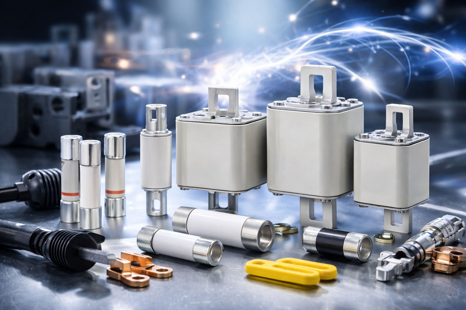
Eaton Bussmann Series Electrical Fuses – Blog & Fachwissen
Im Eaton Bussmann Series Electrical Fuses Blog finden Sie fundiertes Fachwissen rund um elektrische Sicherungen, Überstromschutz und moderne Schutzkonzepte für industrielle und gewerbliche Anwendungen. Diese Kategorie bündelt alle Blogartikel, technischen Beiträge und Praxisguides zu den Sicherungssystemen und Serien von Eaton Bussmann.
Eaton Bussmann zählt weltweit zu den führenden Herstellern von elektrischen Sicherungen, und ihre Serien stehen für Sicherheit, Normkonformität und höchste Zuverlässigkeit in anspruchsvollen elektrischen Systemen.
Was Sie im Eaton Bussmann Sicherungen Blog erwartet
Unsere Blogbeiträge helfen Ingenieuren, Einkäufern, Technikern und Planern dabei, die richtige Sicherungslösung zu finden und technische Zusammenhänge besser zu verstehen.
Themenschwerpunkte dieser Kategorie:
-
🔌 Überblick über Eaton Bussmann Sicherungsserien
-
⚙️ Unterschiede zwischen UL-, IEC- und Spezial-Sicherungen
-
📘 Technische Erklärungen zu Kennlinien, Auslöseverhalten & Bemessungswerten
-
🏭 Anwendungstipps für Industrie, Maschinenbau & Energieverteilung
-
🚗 Beiträge zu EV-, DC- und Hochvolt-Sicherungen
-
🛠 Best Practices für Auswahl, Installation und Wartung
Alle Inhalte sind praxisnah, verständlich aufbereitet und technisch fundiert.
Eaton Bussmann Sicherungsserien im Fokus
Der Blog behandelt regelmäßig verschiedene Eaton Bussmann Series Electrical Fuses, darunter:
-
Industrial Fuses
-
North American (UL) Fuse Series
-
IEC Sicherungsserien
-
High Speed & Semiconductor Fuses
-
EV & DC Sicherungen
-
Supplementary & Specialty Fuses
So erhalten Sie einen umfassenden Überblick über das Eaton Bussmann Portfolio und dessen Einsatzmöglichkeiten.
Fachwissen für sichere elektrische Systeme
Elektrische Sicherungen sind ein zentraler Bestandteil jeder sicheren Stromversorgung. Der Eaton Bussmann Series Electrical Fuses Blog unterstützt Sie dabei, Risiken zu minimieren, Normen einzuhalten und die Lebensdauer Ihrer Anlagen zu verlängern.
Ganz gleich, ob Sie Grundlagenwissen suchen oder tief in spezielle Sicherungsserien eintauchen möchten – hier finden Sie relevante, aktuelle und suchmaschinenoptimierte Inhalte rund um Eaton Bussmann Electrical Fuses.
👉 Jetzt Blogartikel entdecken und Ihr Wissen über Eaton Bussmann Sicherungsserien gezielt erweitern.
- Details
- Category: Electrical Fuses Blog
 eaton-bussmann-series-photovoltaic-fuses-catalogue-ca135004en.pdf  | [Eaton Bussmann PV Fuses] | 0 kB |
Why Does Photovoltaic Fuse Installation Location Matter for Solar Systems?
Solar energy systems rely on multiple electrical components working together safely and efficiently. While solar panels and inverters often receive the most attention during system design, photovoltaic (PV) fuses are equally important for protecting the entire installation against electrical faults and overcurrent conditions.
However, selecting the correct photovoltaic fuse is only part of the process. Its installation location also plays a critical role in determining how effectively the solar system is protected. Incorrect fuse placement can leave important components vulnerable to damage, increase system downtime, and create unnecessary maintenance costs.
So, why does photovoltaic fuse installation location matter for solar systems? Understanding the relationship between fuse placement, electrical current flow, and system protection can help installers and engineers design safer and more reliable solar power installations.
1. Understanding the Importance of Photovoltaic Fuse Installation Location
A photovoltaic fuse is a protective electrical device designed to interrupt excessive current under specified fault conditions. In solar PV systems, it helps protect modules, cables, string circuits, and other electrical equipment from potentially damaging overcurrent.
Unlike conventional electrical installations, solar power systems have unique electrical characteristics. Multiple PV modules are connected in series to form strings, and several strings may be connected in parallel to increase the system's power output.
When multiple strings operate together, fault currents from other parallel strings can flow into a faulty string. Without appropriate overcurrent protection, this reverse current may exceed the safe limits of the affected modules and wiring.
The installation position of a PV fuse determines which section of the electrical circuit receives protection. Therefore, proper placement helps ensure that faults are isolated as close as practical to their source without unnecessarily interrupting other parts of the system.
2. How Photovoltaic Fuse Location Affects System Protection
Correct photovoltaic fuse placement is essential for achieving effective electrical protection. Different installation points serve different purposes depending on the system configuration.
Protecting Individual Solar Panel Strings
String-level protection is particularly important in solar installations containing multiple parallel-connected strings.
When one string develops a fault, current from the other parallel strings may flow backward into the faulty circuit. A properly selected string fuse can interrupt this excessive reverse current before it damages the affected modules or conductors.
Installing appropriate fuses at the string level provides several advantages:
-
Helps prevent excessive reverse current in faulty strings.
-
Reduces the risk of damage to solar modules and cables.
-
Allows the affected string to be isolated without necessarily shutting down the entire solar array.
-
Improves fault identification and maintenance efficiency.
However, string fuses are not required in every PV configuration. Their necessity depends on the number of parallel strings, module specifications, potential reverse current, and applicable electrical standards.
Protecting the Combiner Box
A photovoltaic combiner box brings together the electrical output of multiple solar panel strings before sending it toward the inverter.
String fuses are commonly installed inside the combiner box to provide individual overcurrent protection for the incoming circuits.
The combiner box is an important protection point because it brings multiple electrical paths together. Proper fuse selection and placement help prevent faults in one string from affecting other connected circuits.
Depending on the system design, additional protective devices may also be installed to protect the combined output and associated wiring.
Protecting the Inverter DC Input Circuit
The inverter converts direct current (DC) generated by solar panels into alternating current (AC) for use in electrical installations.
Because the inverter is a critical and often expensive component, protecting its DC input circuit is an important part of solar system design.
Appropriately rated overcurrent protection should be provided where required by the system configuration and applicable electrical standards.
However, a fuse near the inverter does not automatically replace individual string protection. Each protective device must be selected according to the circuit it is intended to protect.
It is also important to understand that a photovoltaic fuse protects against excessive current, not voltage surges. Dedicated surge protection devices are used to address transient overvoltage conditions.
3. What Happens When a Photovoltaic Fuse Is Installed in the Wrong Location?
Incorrect PV fuse installation can compromise the protection and reliability of a solar power system. Even when the fuse itself has the correct electrical ratings, improper positioning may prevent it from protecting the intended circuit effectively.
Here are some common problems associated with incorrect photovoltaic fuse placement.
3.1 Inadequate Protection Against Reverse Current
One of the most important risks in parallel-connected PV strings is reverse current.
If individual string protection is required but not provided, a fault in one string may allow current from other parallel strings to flow into the faulty circuit.
This can result in excessive heating, insulation damage, and potential fire hazards.
Installing correctly rated string fuses helps interrupt this current when it exceeds the permitted protection limits.
3.2 Unnecessary Solar System Shutdowns
Fuse placement also influences how a fault affects overall system operation.
If protection is concentrated at a common point without appropriate branch-level protection, a fault may cause a larger section of the installation to lose power.
By providing suitable protection for individual strings, system designers can improve fault isolation and reduce unnecessary interruptions.
This approach can help maintain the operation of unaffected strings while technicians investigate and repair the faulty circuit.
3.3 Damage to Electrical Cables and Components
A fuse must be installed in the electrical circuit it is intended to protect.
If a section of cable or electrical equipment is not adequately protected, excessive current may cause overheating before the protective device operates.
This is particularly important in solar installations where DC circuits can remain energised whenever sufficient sunlight is available.
Correct fuse positioning, cable sizing, and electrical coordination are therefore essential for reducing the risk of equipment damage.
3.4 Increased Maintenance and Operating Costs
Incorrect fuse placement can make fault detection and troubleshooting more complicated.
When a fault affects multiple strings or a larger section of the system, technicians may need additional time to identify the source of the problem.
Unnecessary shutdowns can also reduce energy production and increase maintenance expenses.
A well-designed photovoltaic protection arrangement helps simplify troubleshooting, minimise downtime, and improve long-term system performance.
4. Key Factors to Consider When Choosing a PV Fuse Installation Location
Selecting the correct installation location requires more than simply following a standard wiring arrangement. Engineers and installers should consider several electrical and environmental factors.
4.1 Solar System Configuration
The number of PV strings, their electrical connections, and the overall system architecture influence fuse placement.
For example, systems with multiple parallel strings generally require greater attention to reverse-current protection than systems containing only one string.
Before installation, it is important to evaluate the potential fault current and determine which circuit sections require individual protection.
4.2 Rated Voltage and Current
A photovoltaic fuse must have suitable voltage and current ratings for the circuit in which it is installed.
Important selection considerations include:
-
Maximum PV system voltage.
-
Module short-circuit current (Isc).
-
Expected operating current.
-
Maximum series fuse rating specified by the module manufacturer.
-
Potential reverse-current contribution from parallel strings.
-
Applicable temperature and installation-related correction factors.
An incorrectly rated fuse may fail to provide reliable protection or operate under unsuitable conditions.
4.3 DC Breaking Capacity
Solar PV systems operate with direct current, which presents different interruption challenges compared with alternating current.
DC arcs do not naturally extinguish at periodic current zero crossings in the same way as AC arcs.
Therefore, photovoltaic fuses must have an appropriate DC voltage rating and breaking capacity for the prospective fault current at their installation point.
Using a fuse designed for an unsuitable electrical application can compromise system safety.
4.4 Environmental Conditions
PV fuse installation locations may be exposed to high temperatures, humidity, dust, and other environmental influences.
These conditions can affect fuse performance and the reliability of electrical connections.
Installers should consider:
-
Ambient operating temperature.
-
Enclosure protection and ventilation.
-
Moisture and dust protection.
-
Proper cable connections.
-
Accessibility for inspection and replacement.
-
Compatibility between the fuse and its holder.
Choosing a suitable enclosure and installation environment helps maintain reliable protection throughout the system's service life.
4.5 Compliance With Electrical Standards
Photovoltaic fuse selection and installation should comply with applicable electrical codes and standards.
For example, IEC 60269-6 addresses supplementary requirements for fuse-links used to protect solar photovoltaic energy systems.
Installers should also consider applicable national regulations, manufacturer instructions, and system design requirements.
Following these requirements helps ensure that the selected fuse provides the intended protection under normal operating and fault conditions.
5. Best Practices for Photovoltaic Fuse Installation
To improve the safety and reliability of solar installations, engineers and electricians should follow several important installation practices.
1. Install string fuses where required.
Evaluate the potential reverse current in parallel-connected strings and install appropriately rated protection when necessary.
2. Use a suitable combiner box.
Ensure that the combiner box provides adequate space, electrical insulation, environmental protection, and appropriate arrangements for string protection.
3. Protect the inverter input circuit appropriately.
Determine the required DC overcurrent protection based on the inverter specifications, circuit design, and applicable regulations.
4. Select photovoltaic-specific fuses.
Use fuses with suitable DC voltage ratings, current ratings, and breaking capacities for the intended PV application.
5. Check fuse coordination.
Ensure that protective devices are properly coordinated with module specifications, conductor ampacity, and other system protection equipment.
6. Follow correct installation procedures.
Use compatible fuse holders, secure electrical connections, and suitable enclosures. Always follow safe isolation procedures before carrying out installation or maintenance work.
7. Conduct regular inspections.
Check for signs of overheating, damaged fuse holders, loose connections, corrosion, and other conditions that could affect electrical protection.
6. How Correct PV Fuse Placement Improves Solar System Performance
Proper photovoltaic fuse installation contributes to more than electrical safety. It also supports the overall efficiency and reliability of solar power systems.
When protective devices are correctly positioned and rated, they can provide several long-term benefits.
-
Improved system safety: Helps reduce the risk of excessive current, cable overheating, and electrical equipment damage.
-
Better fault isolation: Allows faults to be addressed within the affected circuit rather than unnecessarily interrupting the entire installation.
-
Reduced maintenance costs: Makes troubleshooting and component replacement more manageable.
-
Greater equipment protection: Helps protect PV modules, conductors, and other electrical components against specified overcurrent conditions.
-
Improved operational reliability: Reduces avoidable interruptions and supports consistent solar power generation.
Ultimately, the effectiveness of a photovoltaic fuse depends on the combination of correct electrical ratings, suitable installation location, and proper system design.
7. Frequently Asked Questions About Photovoltaic Fuse Installation
Q1: Where should photovoltaic fuses be installed in a solar system?
Photovoltaic fuses are commonly installed at the string level, often inside a combiner box, to protect individual parallel-connected PV strings against excessive reverse current.
Additional overcurrent protection may be required in other DC circuit sections depending on the system configuration, equipment specifications, and applicable electrical regulations.
Q2: Why are string fuses important in solar PV systems?
String fuses help protect individual PV strings against excessive reverse current from other parallel-connected strings.
When a fault occurs, a correctly rated fuse can interrupt the fault current and reduce the risk of damage to modules and cables.
Q3: Does every solar panel string need a fuse?
No. The requirement for string fuses depends on the PV system configuration and the potential reverse current under fault conditions.
The number of parallel strings, module maximum series fuse rating, and applicable electrical standards should all be considered before determining whether string fuses are necessary.
Q4: Can a photovoltaic fuse protect an inverter?
A correctly selected fuse installed in the appropriate DC circuit can provide overcurrent protection for conductors and equipment within its protection scope.
However, a fuse does not protect against every possible inverter fault or voltage surge. Additional protection devices may be necessary depending on the system design.
Q5: What happens if a PV fuse has the wrong current rating?
A fuse with an unsuitable current rating may fail to provide the required protection.
An oversized fuse may not interrupt excessive current quickly enough to protect the circuit, while an undersized fuse may operate unnecessarily during normal conditions.
The fuse rating must be determined using module specifications, operating conditions, conductor ratings, and relevant electrical standards.
Q6: How often should photovoltaic fuses be inspected?
Inspection frequency depends on the installation environment, operating conditions, maintenance plan, and applicable regulations.
Routine inspections should check for visible damage, overheating, corrosion, loose connections, and signs of abnormal operation. Any suspected electrical fault should be investigated by a qualified professional.
Conclusion
Photovoltaic fuse installation location is a critical consideration in solar system design because it directly influences which electrical components receive protection and how effectively faults can be isolated.
From individual PV strings and combiner boxes to inverter DC input circuits, every protective device must be positioned according to the electrical characteristics and requirements of the circuit it serves.
Incorrect fuse placement can leave important components vulnerable to reverse current, excessive heating, and unnecessary system interruptions. In contrast, correctly selected and installed photovoltaic fuses help improve electrical safety, reduce maintenance costs, and support reliable solar power generation.
For installers, engineers, and solar system designers, understanding where and why PV fuses should be installed is an essential step toward building safer, more efficient, and more dependable photovoltaic systems.
- Details
- Category: Electrical Fuses Blog
| eaton-bussmann-series-high-speed-fuses-application-guide-br132015en-en-us.pdf | [Eaton Bussmann Fuses Technical Guide] | 0 kB |
| HSF_Battery-Storage-Application-Guide_June-2020.pdf | [Eaton Bussmann BESS Fuses Technical Guide] | 0 kB |
The Ultimate Guide to Selecting Energy Storage Fuses for Power Distribution Units (PDUs)
Introduction
As renewable energy, battery storage technology, and industrial power infrastructure continue to expand, electrical safety and system reliability have become increasingly important. Power Distribution Units (PDUs) play a critical role in distributing electrical power safely and efficiently across various applications, including Battery Energy Storage Systems (BESS), solar power installations, electric vehicle (EV) charging stations, and industrial facilities.
One of the most important components in ensuring PDU safety is the electrical fuse. Energy storage fuses provide essential protection against overcurrents, short circuits, and potentially dangerous electrical faults. Selecting the wrong fuse can result in equipment damage, unexpected downtime, overheating, and even fire hazards.
However, choosing the right energy storage fuse involves more than simply matching voltage and current ratings. Engineers must consider breaking capacity, time-current characteristics, energy let-through, operating temperature, installation requirements, and applicable safety standards.
This ultimate guide explains how to select the right energy storage fuses for Power Distribution Units, helping engineers, system integrators, and electrical professionals make informed decisions.
1. Understanding the Role of Energy Storage Fuses in PDUs
A Power Distribution Unit is designed to receive electrical power and distribute it to multiple circuits or connected devices. In energy storage applications, PDUs help manage power flow between battery modules, inverters, charging equipment, and other electrical components.
Because these systems may operate with high electrical currents and substantial stored energy, effective circuit protection is essential.
Energy storage fuses are designed to interrupt electrical circuits when current exceeds a predetermined safe level. Their primary purpose is to prevent excessive current from damaging cables, electrical components, battery systems, and sensitive electronic equipment.
Key Functions of Energy Storage Fuses
Overcurrent Protection: Fuses interrupt circuits when excessive current flows through the system, helping prevent overheating and insulation damage.
Short-Circuit Protection: During a short circuit, extremely high fault currents can develop within milliseconds. Properly selected fuses disconnect the affected circuit before serious damage occurs.
Equipment Protection: Sensitive components, including power semiconductor devices, inverters, and battery management systems, require appropriate protection against electrical faults.
Fire Risk Reduction: By limiting fault energy and interrupting dangerous currents, correctly rated fuses help reduce the risk of electrical fires.
System Reliability: Proper circuit protection helps minimise equipment failures, maintenance requirements, and unexpected operational interruptions.
2. Why Proper Fuse Selection Matters for Energy Storage PDUs
Energy storage systems present unique electrical protection challenges. Unlike many conventional AC applications, DC power systems do not naturally experience current zero crossings, making electrical arc interruption particularly challenging.
When a DC circuit develops a fault, the resulting electrical arc can continue unless the protective device is specifically designed and rated to interrupt the DC fault current.
This makes correct fuse selection especially important in battery energy storage systems and DC power distribution applications.
An incorrectly selected fuse may fail to interrupt a fault safely, operate unnecessarily during normal conditions, or provide insufficient protection for connected equipment.
The right energy storage fuse should provide:
-
Reliable interruption of overload and short-circuit currents.
-
Sufficient DC voltage withstand capability.
-
Appropriate breaking capacity for the available fault current.
-
Effective protection for downstream electrical components.
-
Compatibility with the operating environment.
-
Compliance with relevant electrical safety standards.
Selecting a suitable fuse from the beginning helps improve the overall safety, efficiency, and service life of a PDU.
3. Eight Essential Factors to Consider When Selecting Energy Storage Fuses
Choosing an appropriate fuse requires a systematic evaluation of electrical characteristics, environmental conditions, and installation requirements.
The following eight factors provide a practical selection framework.
3.1 Understand Your Application Requirements
The first step is identifying the specific application in which the fuse will operate.
Different energy storage and power distribution systems have different electrical characteristics and protection requirements.
Common applications include:
-
Battery Energy Storage Systems (BESS).
-
Solar photovoltaic power systems.
-
DC power distribution units.
-
Electric vehicle charging infrastructure.
-
Industrial power distribution equipment.
-
Battery charging and conversion systems.
For example, a battery storage system may experience substantial short-circuit currents because of the high energy capacity of its battery modules.
Solar power systems, meanwhile, require protection that accounts for DC operating voltages and potential reverse-current conditions.
Understanding the application helps engineers determine the required voltage rating, current rating, breaking capacity, and fuse operating characteristics.
3.2 Match the Voltage Rating Correctly
Voltage rating is one of the most important considerations when selecting an energy storage fuse.
The fuse voltage rating must be equal to or greater than the maximum voltage that can occur in the protected circuit.
For DC applications, it is particularly important to select a fuse with an appropriate DC voltage rating.
AC and DC fuse ratings should never be assumed interchangeable. Their arc-interruption capabilities can differ significantly.
When evaluating voltage requirements, consider:
-
Maximum battery operating voltage.
-
Fully charged battery voltage.
-
System voltage fluctuations.
-
Maximum DC bus voltage.
-
Transient voltage conditions.
-
Potential voltage increases during abnormal operation.
For example, a fuse designed for a maximum operating voltage of 500V DC may be suitable for a compatible DC distribution circuit, provided its other electrical ratings and application conditions are also appropriate.
Always verify the manufacturer's specified DC voltage rating before installation.
3.3 Select the Appropriate Current Rating
The rated current determines how much current a fuse can carry under specified operating conditions without opening unnecessarily.
Selecting the correct current rating is essential for balancing operational reliability and circuit protection.
A fuse with an insufficient current rating may experience nuisance operation during normal system use.
Conversely, an oversized fuse may not provide adequate protection for connected cables and equipment.
When determining the required current rating, consider:
-
Normal operating current.
-
Maximum continuous load current.
-
Temporary overload conditions.
-
Startup and charging current.
-
Ambient temperature.
-
Cable ampacity.
-
Manufacturer-recommended derating factors.
The fuse rating should be coordinated with the protected conductor and equipment.
It is also important to distinguish between the fuse's rated current and its actual operating current. Fuse performance depends on the relationship between current magnitude, duration, and operating temperature.
3.4 Evaluate Breaking Capacity
Breaking capacity, also known as interrupting capacity, refers to the maximum prospective fault current that a fuse can safely interrupt at its specified operating voltage and conditions.
This is particularly important in battery energy storage applications.
Battery systems can deliver extremely high short-circuit currents because of their low internal resistance and substantial stored energy.
If the prospective fault current exceeds the fuse's breaking capacity, the fuse may not interrupt the fault safely.
This can create serious risks, including:
-
Electrical arcing.
-
Fuse enclosure damage.
-
Equipment destruction.
-
Fire hazards.
-
Potential injury to personnel.
Engineers should calculate or obtain the maximum prospective short-circuit current at the fuse installation point.
The selected fuse must have a breaking capacity greater than or equal to the available fault current under the applicable conditions.
For example, a fuse with a 20kA breaking capacity may be appropriate for a system where the calculated prospective fault current does not exceed that rating, subject to its voltage and other specified operating conditions.
Never select a fuse based solely on its current rating without checking its breaking capacity.
3.5 Consider Operating Temperature and Environmental Conditions
Environmental conditions can significantly influence fuse performance.
Energy storage PDUs may operate in equipment cabinets, industrial environments, outdoor installations, or battery enclosures where temperatures and humidity levels vary.
High ambient temperatures can increase the operating temperature of a fuse and affect its current-carrying capability.
Important environmental factors include:
Ambient Temperature: Elevated temperatures may require current derating to prevent premature fuse operation.
Humidity: High humidity can contribute to corrosion and deterioration of electrical connections and insulation.
Altitude: Increased installation altitude can affect cooling and heat dissipation, potentially influencing electrical component performance.
Vibration: Industrial equipment and mobile energy storage systems may experience vibration that places additional demands on mechanical connections.
Enclosure Conditions: Restricted airflow and compact installation spaces can increase operating temperatures.
Always review the fuse manufacturer's environmental specifications and derating recommendations before finalising the selection.
3.6 Examine Time-Current Characteristics
Time-current characteristics (TCC) describe how quickly a fuse operates at different current levels.
These characteristics are essential for ensuring that a fuse responds appropriately to electrical faults without interrupting normal operating conditions.
For example, a minor overload may require a longer operating time, while a severe short circuit should be interrupted much more quickly.
Understanding the time-current curve helps engineers determine whether the fuse provides adequate protection for the connected equipment.
It also supports coordination between upstream and downstream protective devices.
Proper protection coordination helps ensure that the fuse closest to the fault operates first whenever practical, limiting unnecessary interruption to the rest of the electrical system.
When reviewing time-current characteristics, consider:
-
Normal load current.
-
Expected temporary overloads.
-
Short-circuit current levels.
-
Required fault-clearing time.
-
Coordination with upstream protection.
-
Protection requirements of sensitive electronic components.
A correctly selected fuse should provide an appropriate balance between operational continuity and fault protection.
3.7 Check Energy Let-Through (I²t) Values
Energy let-through, commonly expressed as I²t, represents the thermal energy associated with current flowing through a fuse during its operating process.
It is an important parameter when protecting sensitive electrical components against short-circuit damage.
A fuse with appropriately low let-through energy can help reduce the thermal and mechanical stress experienced by downstream equipment during a fault.
Two important I²t values should be considered:
Pre-Arcing I²t: The energy required to heat and melt the fuse element before an arc develops.
Total Clearing I²t: The total energy let through during the complete interruption process, including the arcing period.
For energy storage PDUs, selecting a fuse with suitable total clearing I²t characteristics can help protect:
-
Semiconductor devices.
-
Power conversion equipment.
-
Battery connections.
-
Electrical conductors.
-
Sensitive electronic components.
However, the lowest I²t value is not automatically the best choice. The fuse must also meet the system's voltage, current, breaking capacity, and coordination requirements.
3.8 Verify Standards and Certifications
Compliance with recognised electrical safety standards is essential when selecting fuses for energy storage and power distribution applications.
Relevant standards help establish requirements for fuse construction, electrical performance, testing, and safety.
Important standards to consider include:
-
IEC 60269: Low-voltage fuses.
-
IEC 60269-1: General requirements for low-voltage fuses.
-
IEC 60269-4: Supplementary requirements for fuse-links protecting semiconductor devices.
-
GB 13539: Chinese low-voltage fuse standards.
-
Applicable UL standards for the intended installation and market.
The exact standard depends on the fuse type, application, and destination market.
Engineers should verify the actual certification documentation, rated voltage, rated current, and test conditions rather than relying solely on general compliance statements.
4. Choosing the Right Fuse Construction and Materials
In addition to electrical ratings, the internal construction and materials of an energy storage fuse influence its performance and reliability.
Several construction features deserve attention.
Silver Fuse Elements
Silver is commonly used in high-performance fuse elements because of its excellent electrical conductivity and predictable melting characteristics.
A properly designed silver fuse element can support reliable operation and consistent fault interruption.
High-Purity Quartz Sand
Quartz sand is frequently used as an arc-quenching material inside high-performance fuse links.
When the fuse element melts and an electrical arc develops, the quartz filling helps absorb heat and support arc extinction.
This is particularly important in DC applications, where arc interruption can be challenging.
Ceramic or Epoxy Enclosures
The fuse enclosure provides electrical insulation and mechanical protection.
Ceramic materials are commonly used because of their heat resistance and insulating properties.
Other enclosure materials may be suitable depending on the fuse design, operating voltage, and application requirements.
The complete fuse assembly must be evaluated to ensure that its construction is appropriate for the intended electrical environment.
5. Understanding Fuse Size and Installation Compatibility
Electrical performance is only one part of successful fuse selection. Physical compatibility is equally important.
A fuse must fit correctly into the designated fuse holder or mounting assembly.
Before purchasing or installing a fuse, verify:
-
Overall fuse dimensions.
-
Terminal configuration.
-
Mounting arrangement.
-
Contact dimensions.
-
Fuse holder compatibility.
-
Required electrical clearances.
-
Thermal installation conditions.
Incorrect physical dimensions can lead to poor electrical contact, excessive resistance, overheating, and potential connection failure.
In high-current PDU applications, proper contact pressure and secure electrical connections are particularly important.
Always use compatible fuse holders and follow the manufacturer's installation instructions.
6. Common Applications of Energy Storage Fuses in PDUs
Energy storage fuses are used across multiple industries where reliable electrical distribution and circuit protection are essential.
6.1 Battery Energy Storage Systems
Battery Energy Storage Systems store electrical energy for later use, supporting renewable energy integration, grid stabilisation, and backup power applications.
Fuses help protect battery modules, DC busbars, and power distribution circuits against overcurrent and short-circuit conditions.
Because battery systems can produce substantial fault currents, breaking capacity and DC voltage ratings are particularly important.
6.2 Solar Photovoltaic Systems
Solar photovoltaic installations generate DC electricity that must be distributed and converted into usable AC power.
Fuses provide protection for photovoltaic strings, DC combiner circuits, and associated power distribution equipment.
Selecting appropriate DC-rated protection helps reduce the risk of damage caused by abnormal current conditions.
6.3 Electric Vehicle Charging Infrastructure
EV charging infrastructure includes power conversion equipment, charging modules, DC distribution circuits, and battery charging interfaces.
Fuses help protect electrical components against short circuits and excessive current.
The selection process must account for operating voltage, continuous current, fault current, and the electrical characteristics of the charging equipment.
6.4 Industrial Power Distribution
Industrial PDUs distribute electrical power to machinery, control systems, production equipment, and other electrical loads.
Reliable fuse protection helps prevent electrical faults from spreading through connected circuits.
Appropriately selected fuses can also reduce equipment damage and minimise production interruptions.
7. Common Mistakes to Avoid When Selecting Energy Storage Fuses
Even experienced electrical professionals can encounter problems when selecting protective devices.
Avoiding the following mistakes can significantly improve system safety and reliability.
Mistake 1: Selecting a Fuse Based Only on Current Rating
A suitable current rating does not guarantee that the fuse can safely interrupt a short circuit. Always verify breaking capacity and voltage rating.
Mistake 2: Ignoring DC Voltage Requirements
DC circuits have different arc-interruption characteristics from AC circuits. Ensure that the selected fuse is explicitly rated for the intended DC application.
Mistake 3: Overlooking Temperature Derating
High ambient temperatures can affect fuse performance. Always consider installation conditions and manufacturer derating recommendations.
Mistake 4: Ignoring I²t Characteristics
An unsuitable energy let-through value may expose sensitive electronic components to excessive thermal stress during a fault.
Mistake 5: Neglecting Protection Coordination
Poor coordination between protective devices can cause unnecessary system shutdowns and reduce operational reliability.
Mistake 6: Using Incompatible Fuse Holders
Incorrect dimensions or unsuitable mounting arrangements can create poor electrical connections and overheating problems.
Mistake 7: Overlooking Applicable Standards
Always verify that the selected fuse meets the regulatory and technical requirements of the intended application.
8. Practical Checklist for Selecting Energy Storage Fuses
Before finalising a fuse selection for a Power Distribution Unit, engineers should review the following checklist:
| Selection Parameter | What to Verify |
|---|---|
| Application | Battery storage, solar, EV charging, or industrial PDU |
| Voltage Rating | Equal to or greater than maximum system voltage |
| Current Rating | Suitable for continuous load and operating conditions |
| Breaking Capacity | Greater than or equal to prospective fault current |
| DC Compatibility | Explicit DC voltage and interruption rating |
| Time-Current Characteristics | Appropriate operating and fault-clearing times |
| I²t Rating | Compatible with downstream equipment withstand limits |
| Operating Temperature | Suitable for actual ambient conditions |
| Environmental Conditions | Humidity, altitude, vibration, and enclosure conditions |
| Standards | Applicable IEC, GB, UL, or other relevant requirements |
| Physical Dimensions | Compatible with fuse holders and mounting arrangements |
| Protection Coordination | Proper coordination with upstream and downstream devices |
Using this checklist can help engineers avoid common selection errors and improve the overall reliability of energy storage power distribution systems.
9. Best Practices for Maintaining Fuse Reliability
Selecting the correct fuse is only the beginning. Regular inspection and maintenance are equally important for ensuring long-term protection performance.
Recommended maintenance practices include:
-
Inspect fuse holders and terminals for signs of overheating.
-
Check electrical connections for looseness or corrosion.
-
Replace damaged or degraded fuse holders.
-
Use replacement fuses with identical approved electrical specifications.
-
Avoid bypassing or modifying protective devices.
-
Follow manufacturer-recommended inspection intervals.
-
Maintain accurate records of fuse ratings and replacement activities.
-
Ensure that maintenance work follows appropriate electrical isolation and safety procedures.
A fuse that has operated under fault conditions should be investigated before replacement. Simply installing a new fuse without identifying the original fault may expose the system to repeated failures.
10. Final Considerations: Building a Safer and More Reliable PDU
Energy storage systems are becoming increasingly important in modern electrical infrastructure. As battery capacities and power distribution requirements continue to grow, selecting appropriate protective devices is essential.
The right energy storage fuse must provide more than basic overcurrent protection. It must offer suitable voltage and current ratings, sufficient breaking capacity, appropriate time-current characteristics, controlled energy let-through, and reliable performance under actual operating conditions.
Engineers should also consider environmental factors, physical compatibility, applicable standards, and coordination with other protective devices.
A systematic selection process helps reduce electrical risks, protect valuable equipment, improve operational reliability, and support the long-term performance of Power Distribution Units.
Ultimately, investing time in proper fuse selection is an important step towards building safer, more efficient, and more dependable energy storage and power distribution systems.
Frequently Asked Questions (FAQs)
1. What is an energy storage fuse?
An energy storage fuse is an electrical protection device designed to interrupt excessive current and short-circuit faults in battery storage systems, DC power distribution equipment, and related electrical installations.
2. Why are fuses important in Power Distribution Units?
Fuses protect PDU circuits and connected equipment against overcurrent and short circuits. They help prevent overheating, electrical damage, and potentially dangerous fault conditions.
3. How do I select the correct fuse voltage rating?
Choose a fuse with a rated voltage equal to or greater than the maximum voltage of the protected circuit. For DC systems, ensure that the fuse has an appropriate DC voltage and interruption rating.
4. What is breaking capacity in a fuse?
Breaking capacity is the maximum prospective fault current that a fuse can safely interrupt under its specified voltage and operating conditions. It must be sufficient for the maximum available short-circuit current at the installation point.
5. What does I²t mean in fuse selection?
I²t represents the thermal energy associated with current flowing through a fuse during operation. It helps engineers evaluate the potential thermal stress imposed on downstream electrical components during a fault.
6. Can an AC fuse be used in a DC power distribution system?
Not automatically. AC and DC applications have different arc-interruption requirements. A fuse must have an appropriate DC voltage and breaking capacity rating for the intended circuit.
7. Which standards should energy storage fuses meet?
Relevant standards may include IEC 60269, GB 13539, and applicable UL standards. The correct requirements depend on the fuse type, application, and installation market.
8. How does ambient temperature affect fuse performance?
High ambient temperatures can increase the fuse's operating temperature and reduce its effective current-carrying capability. Temperature derating should be considered when selecting and installing fuses.
9. What is the difference between pre-arcing I²t and total clearing I²t?
Pre-arcing I²t represents the energy required to melt the fuse element. Total clearing I²t includes both the pre-arcing and arcing periods until the circuit is completely interrupted.
10. How often should energy storage fuses be inspected?
Inspection frequency depends on the operating environment, system design, and manufacturer's maintenance recommendations. Regular inspections should check for overheating, corrosion, damaged components, and loose electrical connections.
- Details
- Category: Electrical Fuses Blog
| eaton-bussmann-series-high-speed-fuses-application-guide-br132015en-en-us.pdf | [Eaton Bussmann Fuses Technical Guide] | 0 kB |
Fuse Selection – How to Confirm Voltage, Current, and Size
Selecting the correct fuse is essential for protecting electrical systems against overcurrent, short circuits, and potential equipment damage. Whether used in solar photovoltaic (PV) installations, electric vehicles, battery energy storage systems, industrial equipment, or communication infrastructure, a properly selected fuse helps ensure electrical safety and reliable system operation.
However, choosing the right fuse involves more than simply matching its current rating to the load. Engineers and electrical professionals must consider several important parameters, including rated voltage, rated current, breaking capacity, physical dimensions, operating temperature, and applicable safety standards.
An incorrectly selected fuse may fail to interrupt a fault current safely, cause unnecessary interruptions, or compromise the protection of connected equipment.
This guide explains how to select a fuse by confirming voltage, current, and size, along with other essential factors to consider before installation.
1. Why Is Correct Fuse Selection Important?
A fuse is a protective electrical component designed to interrupt a circuit when excessive current flows through it. Under normal operating conditions, it allows electrical current to pass through the circuit. When an overload or short circuit occurs, the fuse element heats up and melts, disconnecting the power supply.
Correct fuse selection provides several important benefits:
-
Electrical safety: Helps prevent overheating, electrical fires, and equipment damage.
-
Circuit protection: Interrupts excessive current before it causes serious damage.
-
System reliability: Reduces unnecessary fuse failures during normal operation.
-
Equipment protection: Helps protect sensitive electrical and electronic components.
-
Operational efficiency: Minimises unexpected downtime and maintenance costs.
To achieve these benefits, the fuse must be compatible with the electrical characteristics and operating conditions of the application.
2. How to Confirm the Correct Fuse Voltage Rating
Rated voltage is one of the most important specifications when selecting a fuse.
The voltage rating indicates the maximum circuit voltage at which the fuse is designed to interrupt current safely under specified conditions. Selecting a fuse with an insufficient voltage rating can create serious safety risks.
Understanding Fuse Voltage Ratings
When a fuse interrupts an overload or short circuit, an electrical arc may form between the separated ends of the fuse element.
The fuse must be capable of extinguishing this arc and preventing current from continuing to flow.
If the fuse voltage rating is lower than the maximum circuit voltage, the arc may persist after the fuse element melts. This can result in equipment damage, overheating, or fire.
Therefore, the general selection requirement is:
Fuse Rated Voltage ≥ Maximum System Voltage
For example:
-
A 500V DC system requires a fuse with an appropriate DC voltage rating of at least 500V.
-
A 1000V DC photovoltaic system requires a fuse rated for at least 1000V DC.
-
A 1500V DC solar installation requires a fuse specifically rated for at least 1500V DC.
The selected fuse must also have a suitable breaking capacity for the application.
AC Fuse vs. DC Fuse: What Is the Difference?
One important consideration is whether the electrical system operates on alternating current (AC) or direct current (DC).
In AC circuits, the current naturally passes through zero during each cycle. This zero-crossing characteristic helps extinguish the electrical arc when the fuse operates.
DC circuits do not have the same natural current zero-crossing. Consequently, interrupting DC fault currents can be more challenging, and electrical arcs may continue for longer periods.
For this reason, DC fuse selection requires particular attention to voltage rating and arc-extinguishing performance.
A fuse designed for a specific DC application should be selected according to its rated DC voltage and tested interruption characteristics. An AC voltage rating alone does not establish suitability for DC use.
Key Factors When Checking Fuse Voltage
Before selecting a fuse, confirm:
-
The maximum operating voltage of the electrical system.
-
Whether the application uses AC or DC power.
-
The fuse's rated voltage for the relevant current type.
-
The maximum voltage that may occur under operating conditions.
-
Whether the fuse is specifically approved for the intended application.
For solar PV systems, battery storage installations, and electric vehicle applications, using an appropriately rated DC fuse is particularly important.
3. How to Determine the Correct Fuse Current Rating
Current rating is another essential factor in fuse selection.
The rated current indicates the current a fuse can carry under specified operating conditions. A correctly selected fuse should withstand normal operating current without unnecessary interruptions while providing protection when an abnormal current condition occurs.
Selecting an undersized fuse may cause frequent blowing during normal operation. Conversely, an oversized fuse may not provide adequate protection for the connected cables and equipment.
Calculate the Normal Operating Current
The first step is to determine the circuit's normal operating current.
For DC systems, current can generally be calculated using:
I = P / V
Where:
-
I = Current in amperes (A)
-
P = Power in watts (W)
-
V = Voltage in volts (V)
For example, consider a DC system with:
-
Power: 2,000 W
-
Operating voltage: 400 V
The operating current is:
I = 2,000 / 400
I = 5 A
The calculated normal operating current is 5 amperes.
This value provides a starting point for selecting an appropriate fuse. However, the final fuse rating must also account for load characteristics, conductor protection, temperature, and manufacturer specifications.
Apply the Appropriate Safety Margin
A commonly used preliminary selection guideline is to consider a fuse rated at approximately 1.6–2.5 times the normal operating current.
For example, if the normal operating current is 10 A, this guideline produces a preliminary range of:
10 × 1.6 = 16 A
10 × 2.5 = 25 A
This gives a preliminary range of 16–25 A.
However, this multiplier is not a universal fuse-sizing rule. The correct rating depends on the application, applicable electrical standards, fuse time-current characteristics, cable ampacity, and the manufacturer's recommendations.
In particular, the selected fuse must not exceed the maximum permitted protection rating of the conductors or connected equipment.
Consider Ambient Temperature
Temperature has a significant influence on fuse performance.
As ambient temperature increases, the fuse element may operate closer to its melting temperature. This can reduce the current-carrying capability of the fuse and cause premature operation.
When selecting a fuse for high-temperature environments, consider the manufacturer's temperature derating curves.
Important environmental factors include:
-
Ambient operating temperature.
-
Enclosure temperature.
-
Ventilation and heat dissipation.
-
Installation position.
-
Heat generated by neighbouring components.
A fuse installed inside a compact electrical enclosure may experience higher temperatures than one installed in an open, well-ventilated environment.
Consider Starting and Inrush Current
Some electrical loads temporarily draw higher current during startup.
Examples include motors, transformers, capacitors, and certain electronic power supplies.
If the fuse cannot tolerate these temporary current surges, it may blow unnecessarily during normal equipment startup.
In these situations, engineers should evaluate the load's inrush current and duration before choosing between fast-acting and time-delay fuse characteristics.
4. How to Confirm the Correct Fuse Size
Physical dimensions are just as important as electrical ratings.
Even when a fuse has the correct voltage and current specifications, it may not fit the existing fuse holder or installation space.
Using an incompatible fuse size can create poor electrical contact, increased resistance, overheating, and installation difficulties.
Common Fuse Dimensions
Different applications require different fuse formats and mounting configurations.
Common fuse dimensions include:
| Fuse Size | Typical Application |
|---|---|
| 10 × 38 mm | Compact photovoltaic and electrical protection systems |
| 14 × 51 mm | Medium-sized PV and industrial installations |
| 22 × 58 mm | Higher-current electrical protection applications |
| NH fuse sizes | Industrial power distribution systems |
These dimensions generally refer to the physical length and diameter of cylindrical fuse links or the corresponding dimensions of other fuse formats.
The exact specifications depend on the fuse design.
Check Fuse Holder Compatibility
The fuse must be mechanically and electrically compatible with its holder.
Before purchasing a replacement or selecting a new fuse, verify:
-
Overall fuse length.
-
Fuse body diameter or dimensions.
-
Terminal configuration.
-
Contact design.
-
Mounting method.
-
Fuse holder compatibility.
-
Available installation space.
For example, a cylindrical fuse measuring 10 × 38 mm cannot automatically replace a 14 × 51 mm fuse, even if both have similar electrical ratings.
The fuse holder must also be rated for the required voltage and current.
Check the Manufacturer's Technical Documentation
The most reliable way to confirm fuse dimensions is to consult the equipment's technical documentation.
Product datasheets typically provide:
-
Rated voltage.
-
Rated current.
-
Breaking capacity.
-
Physical dimensions.
-
Mounting requirements.
-
Operating temperature range.
-
Applicable standards.
Always verify these details before installation.
5. Why Breaking Capacity Matters in Fuse Selection
Breaking capacity, also known as interrupting capacity, is an essential specification that should never be overlooked.
It refers to the maximum prospective fault current that a fuse can safely interrupt under its specified operating conditions.
During a short circuit, the current can rise significantly above the normal operating level. The fuse must be capable of interrupting this fault current without rupturing or creating an electrical hazard.
The general selection requirement is:
Fuse Breaking Capacity ≥ Maximum Prospective Short-Circuit Current
For example, if the maximum prospective short-circuit current in a circuit is 20 kA, the selected fuse must have an adequate breaking capacity of at least 20 kA at the applicable voltage and conditions.
Breaking capacity is especially important in:
-
Solar photovoltaic systems.
-
Battery energy storage systems.
-
Electric vehicle power circuits.
-
Industrial distribution panels.
-
High-current DC applications.
A fuse with an insufficient breaking capacity may fail dangerously during a severe short-circuit event.
6. How to Choose Between Fast-Acting and Time-Delay Fuses
Fuse operating characteristics also influence the selection process.
Different electrical loads have different current profiles. Therefore, the fuse must respond appropriately to both normal operating conditions and abnormal current increases.
Fast-Acting Fuses
Fast-acting fuses are designed to interrupt excessive current quickly.
They are commonly used in applications where sensitive components require rapid overcurrent protection.
Typical applications include:
-
Electronic circuits.
-
Semiconductor protection.
-
Sensitive electrical equipment.
-
Certain power supply circuits.
Time-Delay Fuses
Time-delay fuses can withstand temporary current surges for a specified period without operating unnecessarily.
They are suitable for applications involving startup currents or short-duration current peaks.
Typical applications include:
-
Electric motors.
-
Transformers.
-
Capacitive loads.
-
Equipment with high startup current.
The correct choice depends on the load's characteristics, required protection coordination, and the equipment manufacturer's recommendations.
7. Check Applicable Fuse Standards and Certifications
Compliance with recognised safety standards is another important part of fuse selection.
Standards establish requirements for electrical performance, construction, testing, and safety.
Depending on the application, relevant standards may include:
-
IEC 60269: Low-voltage fuses and their general requirements.
-
IEC 60269-6: Additional requirements for fuse links used to protect solar photovoltaic energy systems.
-
UL standards: Applicable safety and performance requirements for electrical components.
-
GB standards: Relevant Chinese national standards for electrical protection products.
Certifications and compliance documentation help demonstrate that a fuse has been evaluated against the requirements of its intended application.
However, certification marks should always be checked against the exact product model and relevant certification scope.
Selecting a fuse that meets the applicable standards helps improve system safety, reliability, and compatibility with equipment requirements.
8. Common Fuse Selection Mistakes to Avoid
Even experienced electrical professionals can make mistakes when selecting protective components.
Understanding common problems can help prevent unnecessary failures and improve electrical system protection.
1. Choosing the Wrong Voltage Rating
Using a fuse with an insufficient voltage rating may prevent it from safely interrupting fault current.
Always verify the maximum system voltage and the fuse's AC or DC rating.
2. Selecting an Incorrect Current Rating
A fuse with an excessively low current rating may blow during normal operation. An excessively high rating may compromise circuit protection.
Calculate the operating current and consider all relevant derating and protection requirements.
3. Ignoring Temperature Derating
High ambient temperatures can affect fuse performance.
Always check the manufacturer's derating information when operating conditions involve elevated temperatures.
4. Overlooking Breaking Capacity
A fuse may have the correct rated current but insufficient breaking capacity.
Verify the maximum prospective short-circuit current before finalising the selection.
5. Using an Incompatible Fuse Size
A fuse that does not fit the holder correctly may create poor contact and overheating.
Confirm the dimensions and terminal configuration before installation.
6. Ignoring Operating Characteristics
Selecting a fast-acting fuse for a load with significant startup current may result in nuisance blowing.
Evaluate the load's current profile and select the appropriate time-current characteristic.
9. Practical Fuse Selection Checklist
Before choosing or replacing a fuse, use the following checklist to verify the essential specifications.
| Selection Parameter | What to Confirm |
|---|---|
| Rated Voltage | Must meet or exceed the maximum circuit voltage |
| Rated Current | Must accommodate normal load current while providing appropriate protection |
| Current Derating | Consider ambient temperature and installation conditions |
| Breaking Capacity | Must meet or exceed the maximum prospective short-circuit current |
| Fuse Dimensions | Confirm length, diameter, and physical configuration |
| Fuse Holder | Ensure electrical and mechanical compatibility |
| Operating Characteristics | Select fast-acting or time-delay according to load requirements |
| Applicable Standards | Verify relevant IEC, UL, or other required compliance |
| Application | Confirm suitability for PV, EV, energy storage, or industrial use |
Checking these parameters systematically helps reduce selection errors and supports reliable electrical protection.
10. Conclusion: How to Select the Right Fuse
Correct fuse selection requires careful evaluation of electrical ratings, physical specifications, and operating conditions.
The three fundamental parameters are voltage, current, and size. The voltage rating must be suitable for the maximum circuit voltage, the current rating must provide appropriate protection under normal and fault conditions, and the physical dimensions must match the installation and fuse holder.
However, reliable fuse selection also requires attention to breaking capacity, temperature derating, time-current characteristics, and applicable safety standards.
Whether designing a photovoltaic installation, electric vehicle electrical system, battery energy storage solution, or industrial power distribution network, selecting the correct fuse is essential for protecting equipment and maintaining safe operation.
By following a systematic selection process and consulting the relevant technical documentation, engineers and installers can make more informed decisions and improve the long-term reliability of electrical systems.
Frequently Asked Questions (FAQs)
1. How do I know which fuse voltage rating I need?
Determine the maximum operating voltage of the circuit and select a fuse with a rated voltage equal to or higher than that value. Make sure the rating is suitable for AC or DC operation, as applicable.
2. How do I calculate the correct fuse current rating?
For a DC circuit, calculate the operating current using I = P / V. Then consider the load characteristics, temperature derating, conductor ampacity, and applicable fuse-sizing requirements to determine the appropriate fuse rating.
3. Can I replace a fuse with one that has a higher current rating?
Not without verifying that the higher rating is permitted by the circuit design and equipment specifications. An oversized fuse may fail to provide adequate protection for cables and connected components.
4. Can an AC fuse be used in a DC circuit?
Not automatically. The fuse must have an appropriate DC voltage rating and sufficient DC breaking capacity. An AC rating alone does not guarantee safe DC interruption.
5. What does 10 × 38 mm mean on a fuse?
It generally refers to the physical dimensions of a cylindrical fuse, with a length of approximately 38 mm and a diameter of approximately 10 mm.
6. Why is fuse breaking capacity important?
Breaking capacity determines the maximum fault current a fuse can safely interrupt under specified conditions. Selecting sufficient breaking capacity helps prevent dangerous failures during short circuits.
7. Does ambient temperature affect fuse selection?
Yes. High ambient temperatures can reduce a fuse's current-carrying capability and affect its operating characteristics. Temperature derating should be considered during selection.
8. What is the difference between a fast-acting and a time-delay fuse?
A fast-acting fuse interrupts excessive current quickly, making it suitable for sensitive circuits. A time-delay fuse tolerates specified temporary current surges, making it useful for loads with high startup currents.
- Details
- Category: Electrical Fuses Blog
| eaton-bussmann-series-high-speed-fuses-application-guide-br132015en-en-us.pdf | [Eaton Bussmann Fuses Technical Guide] | 0 kB |
Why Are Fuses Single-Use? Understanding the Science Behind Fuse Protection
Fuses are essential safety components in electrical systems, protecting equipment, wiring, and circuits from potentially dangerous electrical faults. Whether used in household appliances, industrial machinery, solar power systems, or energy storage installations, fuses play a crucial role in preventing damage caused by excessive electrical current.
One common question people ask is: Why are fuses single-use? Why can't a blown fuse simply be reset and used again?
The answer lies in their fundamental working principle. Unlike reusable circuit protection devices, traditional electrical fuses are specifically designed to sacrifice their internal fuse element when an electrical fault occurs. This intentional design allows them to interrupt dangerous currents quickly and reliably.
In this article, we explore how fuses work, why they cannot be reused after blowing, and the advantages of their single-use design in modern electrical applications.
1. How Does an Electrical Fuse Work?
To understand why fuses are single-use, it is important to understand their basic operating principle.
An electrical fuse contains a specially designed metal element that melts when the current flowing through it exceeds a predetermined level for a sufficient period.
The working process follows four basic stages:
Current → Heat → Melting → Circuit Interruption
Under normal operating conditions, the fuse element carries electrical current without overheating. However, when an overload or short circuit occurs, the current increases beyond the fuse's rated operating conditions.
This excessive current generates heat within the fuse element. Once the temperature reaches its melting point, the metal element melts and breaks the electrical connection.
As a result, the circuit is interrupted, stopping the flow of dangerous current and protecting connected equipment from further damage.
The melting process is irreversible. Once the internal fuse element has melted, the original electrical connection cannot be restored. This is the primary reason why a conventional fuse must be replaced after it blows.
2. Why Are Fuses Designed for Single Use?
The single-use design of electrical fuses is intentional. It provides several important safety and performance advantages.
2.1 Fast Response to Electrical Faults
One of the biggest advantages of a fuse is its ability to respond quickly to excessive electrical current.
When a short circuit or severe overload occurs, the fuse element heats up and melts according to its designed time-current characteristics.
Unlike mechanical protection devices, a conventional fuse does not require moving components, springs, or electromagnetic mechanisms to operate.
This simple physical process allows appropriately selected fuses to interrupt fault currents very quickly.
Fast fault interruption is particularly important in electrical systems where excessive current can damage sensitive components, power equipment, or electrical wiring.
2.2 Reliable Protection Without Moving Parts
Traditional fuses have a relatively simple internal structure.
Their operation depends primarily on the electrical and thermal properties of the fuse element. Since they do not rely on complex mechanical mechanisms, there are fewer components that can wear out or become stuck.
This simplicity contributes to their reliability in demanding environments.
Fuses are commonly used in:
-
Industrial electrical installations.
-
Solar photovoltaic power systems.
-
Battery energy storage systems.
-
Electric vehicle electrical systems.
-
Power distribution equipment.
-
Electrical control panels.
In these applications, dependable circuit protection is essential for maintaining safe and stable operation.
2.3 A Clear Indication of Electrical Faults
Another important advantage of single-use fuses is that they provide a clear indication that an electrical fault has occurred.
When a fuse blows, the interruption of the circuit signals that the system has experienced an abnormal electrical condition.
This encourages users and maintenance personnel to investigate the underlying problem before restoring power.
By comparison, repeatedly resetting a protection device without identifying the cause of the fault may allow an underlying electrical problem to remain unresolved.
Therefore, replacing a blown fuse is not simply a maintenance task. It is also an important opportunity to inspect the electrical system and identify potential safety issues.
2.4 Cost-Effective Circuit Protection
Fuses are generally economical electrical protection components.
Their simple construction makes them relatively inexpensive to manufacture, install, and replace.
They also require little routine maintenance under normal operating conditions.
For electrical installations involving multiple protection points, this makes fuses a practical solution for providing reliable overcurrent protection without introducing unnecessary mechanical complexity.
3. Why Can't a Blown Fuse Be Reused?
A conventional fuse cannot be reused because its internal protective element is physically damaged during operation.
When excessive current causes the element to melt, the electrical connection is permanently interrupted.
Unlike a circuit breaker, which uses a mechanical switching mechanism that can be reset, a traditional fuse has no mechanism for reconnecting its melted element.
Attempting to reuse a blown fuse can create serious electrical safety risks.
For example:
-
Damaged fuse elements: A melted fuse element cannot reliably carry electrical current again.
-
Unpredictable protection: Repairing or modifying a fuse may change its current-carrying and interruption characteristics.
-
Increased fire risk: Improper repairs can cause overheating and electrical fires.
-
Equipment damage: An incorrectly repaired fuse may fail to interrupt dangerous fault currents.
For these reasons, a blown fuse should always be replaced rather than repaired or reused.
Never replace a fuse element with copper wire, metal strips, or other improvised materials. These substitutes do not provide the controlled melting characteristics required for safe circuit protection.
4. Fuse vs. Circuit Breaker: What Is the Difference?
Both fuses and circuit breakers protect electrical circuits against excessive current. However, they operate differently.
Understanding these differences helps explain why single-use fuses remain widely used despite the availability of resettable circuit breakers.
| Feature | Electrical Fuse | Circuit Breaker |
|---|---|---|
| Operating principle | Melting of a metal element | Mechanical or electronic tripping mechanism |
| Reusability | Single-use | Generally resettable |
| Moving parts | No moving parts in the fuse element | Mechanical components in conventional designs |
| Fault response | Can provide very fast interruption | Depends on breaker design and characteristics |
| Maintenance | Replacement after operation | Inspection and resetting when appropriate |
| Cost | Generally economical | Often higher initial cost |
| Fault indication | Physical interruption of the fuse element | Trip indication or switching position |
Neither protection method is universally better.
The appropriate choice depends on the electrical system, operating conditions, required interruption capacity, protection coordination, and maintenance requirements.
In some applications, fuses are preferred because of their straightforward construction, dependable operation, and high fault-current interruption capabilities.
5. Why Are Single-Use Fuses Important in Solar Power Systems?
Solar photovoltaic systems require reliable electrical protection because they operate under specific voltage and current conditions.
Photovoltaic installations often contain multiple solar panels connected in series and parallel configurations. Under certain fault conditions, excessive current can damage cables, connectors, modules, and other electrical components.
Solar PV fuses help protect these circuits by interrupting abnormal current before it causes more extensive damage.
Their single-use design offers several advantages:
Fast fault interruption: Properly selected photovoltaic fuses can interrupt dangerous overcurrent conditions quickly.
Reliable operation: Their simple construction supports dependable protection in electrical installations.
Equipment protection: They help reduce the risk of damage to photovoltaic modules, cables, and associated electrical equipment.
Fault identification: A blown fuse indicates that the protected circuit requires investigation.
It is important to select photovoltaic fuses according to the system's operating voltage, current, temperature conditions, and applicable electrical standards.
DC applications also require particular attention to rated voltage and arc interruption capability because direct current does not naturally pass through zero as alternating current does.
6. What Should You Do When a Fuse Blows?
When a fuse blows, replacing it immediately without investigating the cause is not always the safest approach.
Follow these basic precautions:
Step 1: Disconnect the Power Supply
Switch off the appropriate power source and isolate the affected circuit. Follow the equipment manufacturer's safety procedures and verify that the circuit is de-energised before inspection.
Step 2: Identify the Cause of the Fault
Investigate possible causes, including:
-
Electrical overloads.
-
Short circuits.
-
Damaged cables or insulation.
-
Faulty electrical equipment.
-
Loose electrical connections.
-
Deteriorated wiring.
Step 3: Replace the Fuse With the Correct Specification
Use a replacement fuse with the correct rated current, voltage, breaking capacity, size, and operating characteristics.
Never install a fuse with a higher current rating simply to prevent repeated blowing.
Step 4: Check the Electrical System
Before restoring power, ensure that the underlying fault has been identified and corrected.
If the replacement fuse blows again, stop using the circuit and arrange for a qualified electrician or electrical technician to investigate.
Repeated fuse failures often indicate an unresolved electrical problem.
7. How to Choose the Right Replacement Fuse
Selecting the correct replacement fuse is essential for maintaining electrical safety and system reliability.
Several technical factors should be considered.
Rated Current
The rated current indicates the current a fuse is designed to carry under specified operating conditions.
A fuse with an incorrect current rating may provide inadequate protection or interrupt normal operation unnecessarily.
Rated Voltage
The fuse voltage rating must be suitable for the circuit in which it is installed.
This is especially important in DC applications, where interrupting an electrical arc can present additional challenges.
Breaking Capacity
Breaking capacity refers to the maximum prospective fault current that a fuse can safely interrupt under its specified conditions.
The selected fuse must have an adequate breaking capacity for the installation.
Fuse Size and Dimensions
The physical dimensions must match the fuse holder or installation requirements.
Incorrect dimensions can result in poor electrical contact, overheating, or installation problems.
Operating Characteristics
Different applications require different fuse characteristics.
Time-current curves, pre-arcing characteristics, and total clearing performance should be considered when selecting a fuse for a particular electrical system.
Choosing a fuse based only on its current rating is not sufficient. All relevant electrical and installation requirements must be evaluated.
8. Are All Electrical Fuses Single-Use?
Traditional melting-element fuses are designed for single-use operation. Once their internal element melts, the fuse must be replaced.
However, not every overcurrent protection device works in the same way.
Resettable circuit breakers use mechanical or electronic mechanisms to interrupt current and can generally be returned to service after the fault has been investigated and cleared.
There are also resettable electronic protection devices and polymer-based resettable components used in certain applications.
These devices have different operating principles and should not be confused with conventional electrical fuses.
The key distinction is that a traditional fuse provides protection by permanently interrupting its internal conductive element.
Conclusion: Why Single-Use Fuses Remain Essential for Electrical Safety
Fuses are single-use because their protective function depends on the controlled melting of an internal metal element.
When an overload or short circuit occurs, this element melts and permanently interrupts the electrical connection, preventing excessive current from continuing to flow through the protected circuit.
Although replacing a blown fuse may seem less convenient than resetting a circuit breaker, this single-use design offers important advantages, including fast fault interruption, simple construction, reliable operation, and clear fault indication.
From industrial electrical installations to solar photovoltaic systems and energy storage applications, conventional fuses continue to play an important role in protecting electrical equipment and improving system safety.
Understanding why fuses cannot be reused is essential for anyone involved in electrical installation, maintenance, or equipment operation. Always replace a blown fuse with one that meets the original specifications, and investigate the underlying fault before restoring power.
- Details
- Category: Electrical Fuses Blog
| eaton-bussmann-series-nh-phovoltaic-fuses-datasheet-720133-en-us.pdf | [Eaton Bussmann PV Fuses] | 0 kB |
Working Principle of PV Connector: How Does a Solar PV Connector Work?
Introduction
Solar photovoltaic (PV) systems rely on several electrical components to convert sunlight into usable electricity. Among these components, the PV connector plays an essential role in ensuring safe, efficient, and reliable power transmission. Although relatively small, it is responsible for establishing secure electrical connections between solar panels, cables, inverters, and other system components.
Understanding the working principle of a PV connector is important for solar installers, system designers, electrical engineers, and solar equipment users. A properly designed connector helps minimise power losses, maintain electrical stability, and protect the photovoltaic system against environmental conditions.
But how does a PV connector work? What makes it suitable for outdoor solar installations?
This article explores the working principle of PV connectors, their main components, electrical conduction mechanisms, environmental protection features, and mechanical design.
1. What Is a PV Connector?
A photovoltaic connector, commonly known as a PV connector or solar connector, is an electrical connection device specifically designed for solar power systems. Its primary function is to connect solar panels with other electrical components while maintaining a stable and low-resistance electrical connection.
PV connectors are commonly used to connect:
-
Solar panels within a photovoltaic array.
-
Solar panel strings to DC cables.
-
DC cables to solar inverters.
-
Photovoltaic modules to combiner boxes.
-
Solar panels to compatible energy storage systems.
Unlike ordinary electrical connectors, PV connectors are designed to withstand outdoor environmental conditions, including ultraviolet radiation, moisture, dust, temperature fluctuations, and mechanical stress.
Their construction ensures that electricity can flow continuously and safely throughout the solar power system.
2. Working Principle of a PV Connector
The working principle of a PV connector is based on electrical conduction, secure mechanical contact, and protective insulation.
Solar panels generate direct current (DC) electricity when exposed to sunlight. This electricity must travel through connecting cables to reach an inverter or other electrical equipment.
A PV connector establishes the electrical connection between these components. Its internal conductive contacts create a low-resistance pathway that allows electrical current to flow efficiently.
The working process can be divided into four main stages:
2.1 Electrical Contact and Current Conduction
The first and most important function of a PV connector is to establish an effective electrical connection.
Inside the connector, conductive metal terminals provide the pathway for current transmission. These terminals are commonly manufactured from copper alloys with suitable conductive coatings, such as tin plating.
High-quality conductive materials offer several advantages:
-
Low electrical resistance.
-
Efficient current transmission.
-
Reduced energy losses.
-
Improved resistance to corrosion.
-
Stable electrical performance over time.
When two compatible connector components are properly assembled, their conductive contacts form a secure electrical connection.
The contact design and contact pressure help maintain electrical continuity and prevent unstable connections.
A low-resistance connection is particularly important because excessive resistance can generate heat and reduce the overall efficiency of a photovoltaic system.
2.2 Environmental Sealing and Insulation Protection
Solar PV connectors are generally installed outdoors, where they are exposed to changing weather conditions.
Rain, humidity, dust, sunlight, and temperature variations can damage electrical connections if adequate protection is not provided.
To prevent these problems, PV connectors incorporate specialised sealing and insulation structures.
Their protective features typically include:
Waterproof Sealing
Rubber sealing rings and other protective components create barriers against moisture entering the connector housing.
Depending on the product design, PV connectors may achieve IP67 or IP68 ingress protection ratings. These ratings indicate specific levels of protection against dust and water under defined testing conditions.
Dust Protection
The connector housing and sealing structure help prevent dust and other particles from reaching the internal conductive components.
UV Resistance
Solar connectors must withstand prolonged exposure to sunlight. UV-resistant insulating materials help prevent premature ageing, cracking, and deterioration.
Electrical Insulation
The insulating housing separates conductive components from the external environment and helps prevent accidental electrical contact, leakage currents, and short circuits.
Together, these features improve connector reliability and help maintain safe electrical performance in outdoor installations.
2.3 Mechanical Locking Ensures a Secure Connection
Electrical performance depends not only on conductive materials but also on mechanical stability.
PV connectors use locking mechanisms to keep their male and female components securely connected.
Common locking structures include snap-fit locking mechanisms and threaded coupling designs.
When the connector components are joined correctly, the locking mechanism prevents accidental separation.
This is important because solar installations may experience:
-
Wind-induced vibrations.
-
Mechanical movement.
-
Thermal expansion and contraction.
-
Cable tension.
-
Accidental physical impacts.
A loose connector can increase contact resistance, generate excessive heat, and potentially cause electrical failures.
The mechanical locking structure therefore helps maintain a stable connection throughout the operating life of the solar installation.
2.4 Voltage and Current Compatibility
Every PV connector is designed to operate within specified electrical ratings.
These ratings typically include maximum operating voltage, rated current, contact resistance, and temperature limits.
For example, photovoltaic systems may operate at different DC voltage levels, including 1000V DC and 1500V DC.
The connector must be suitable for the electrical characteristics of the system in which it is installed.
Important design considerations include:
-
Conductor cross-sectional area.
-
Terminal contact structure.
-
Insulation thickness.
-
Dielectric strength.
-
Rated current capacity.
-
Temperature resistance.
Using a connector with an insufficient voltage or current rating can lead to insulation breakdown, overheating, or electrical hazards.
Therefore, selecting a PV connector that matches the electrical requirements of the solar installation is essential.
3. Main Components of a PV Connector
To understand how a PV connector works, it is helpful to examine its main structural components.
3.1 Male Connector
The male connector contains a conductive metal contact designed to connect with the corresponding female terminal.
Its housing provides mechanical support and electrical insulation.
3.2 Female Connector
The female connector contains a compatible conductive contact that receives the male terminal.
The internal contact structure is designed to maintain reliable electrical contact and minimise resistance.
3.3 Conductive Metal Contacts
Metal contacts are responsible for transmitting electrical current between connected cables and photovoltaic equipment.
Copper-based conductive materials are commonly used because of their favourable electrical conductivity.
3.4 Insulating Housing
The external housing protects the internal electrical components.
It is generally manufactured from durable insulating materials that provide electrical isolation, mechanical strength, and resistance to outdoor environmental conditions.
3.5 Sealing Rings
Sealing rings help prevent water and dust from entering the connector.
They are an important part of the connector's environmental protection system.
3.6 Locking Mechanism
The locking structure secures the male and female connector components together.
It helps prevent accidental disconnection and maintains mechanical stability during operation.
4. Why Is Low Contact Resistance Important in PV Connectors?
Contact resistance is one of the most important factors affecting the performance of a photovoltaic connector.
When electrical current passes through a connector, some energy is converted into heat because of electrical resistance.
This relationship can be explained using the following formula:
P = I²R
Where:
-
P = Power loss in watts.
-
I = Electrical current in amperes.
-
R = Electrical resistance in ohms.
The formula shows that power loss increases with the square of the current.
For this reason, even a relatively small increase in contact resistance can result in significant heat generation, particularly in high-current photovoltaic applications.
Excessive contact resistance may cause:
-
Increased connector temperature.
-
Reduced energy transmission efficiency.
-
Accelerated material ageing.
-
Insulation deterioration.
-
Potential connector failure.
High-quality PV connectors are therefore designed with suitable conductive materials, optimised contact structures, and reliable mechanical connections to minimise contact resistance.
5. How Do PV Connectors Improve Solar System Safety?
Electrical safety is a critical consideration in photovoltaic installations.
PV connectors contribute to system safety through several important design features.
Secure Electrical Connections
Properly assembled connectors maintain stable electrical contact and reduce the risk of intermittent connections.
Insulation Protection
Insulating materials prevent unintended contact with conductive components and help maintain electrical separation.
Water and Dust Resistance
Sealing structures reduce the possibility of moisture and dust entering the electrical connection.
Mechanical Locking
Locking mechanisms help prevent accidental disconnection caused by vibration or mechanical movement.
Electrical Rating Compatibility
Selecting connectors with appropriate voltage and current ratings helps prevent overheating and insulation damage.
It is important to remember that connector safety also depends on correct installation. Improper crimping, incompatible connector combinations, damaged seals, and incorrect cable preparation can compromise performance.
6. Factors to Consider When Selecting a PV Connector
Choosing the correct PV connector is essential for maintaining long-term solar system performance.
Several factors should be evaluated before selecting a connector.
6.1 Rated Voltage
The connector's maximum rated voltage must meet or exceed the maximum system voltage under the relevant operating conditions.
6.2 Rated Current
The connector must be capable of carrying the expected operating current without exceeding its specified temperature limits.
6.3 Contact Resistance
Low contact resistance helps minimise energy losses and excessive heat generation.
6.4 Protection Rating
The ingress protection rating should be suitable for the environmental conditions and installation requirements.
6.5 Temperature Resistance
The connector must withstand the temperature variations expected during normal operation.
6.6 Material Quality
Conductive contacts should provide good electrical conductivity and corrosion resistance, while the housing should offer suitable insulation and weather resistance.
6.7 Connector Compatibility
Connectors should be designed and certified for use together. Physical fit alone does not establish electrical or safety compatibility.
Mixing connector components from different manufacturers or product families should be avoided unless their compatibility has been specifically confirmed.
7. Common Problems Associated with PV Connectors
Although PV connectors are designed for long-term outdoor operation, improper selection, installation, or maintenance can lead to problems.
Some common issues include:
Loose Connections
Poor mechanical engagement can increase contact resistance and generate excessive heat.
Incorrect Crimping
Improper cable crimping may result in weak electrical contact, increased resistance, or cable separation.
Water Ingress
Damaged sealing rings or incorrectly assembled connector housings can allow moisture to enter.
Connector Incompatibility
Using incompatible connector components can compromise electrical contact and mechanical locking.
Overheating
Excessive current, poor contact quality, and unsuitable connector ratings may cause abnormal temperature increases.
Regular inspection, correct installation procedures, and the use of compatible components help reduce these risks.
8. Conclusion
The working principle of a PV connector combines efficient electrical conduction, environmental protection, mechanical locking, and electrical compatibility.
By providing a secure, low-resistance connection between solar panels and other photovoltaic equipment, PV connectors help maintain efficient power transmission and improve overall system reliability.
Their conductive contacts support continuous current flow, insulating housings provide electrical protection, sealing structures prevent environmental damage, and locking mechanisms maintain mechanical stability.
For solar installers, system designers, and photovoltaic equipment users, understanding how PV connectors work is essential for selecting suitable components and ensuring reliable solar installations.
Ultimately, a properly selected and correctly installed PV connector contributes significantly to the safety, efficiency, and long-term performance of a photovoltaic power system.
Frequently Asked Questions (FAQs)
1. What is the main function of a PV connector?
The main function of a PV connector is to establish a secure electrical connection between solar panels, DC cables, inverters, and other photovoltaic system components. It enables efficient transmission of direct current while providing electrical insulation and environmental protection.
2. How does a solar PV connector work?
A solar PV connector works by joining compatible conductive metal contacts inside insulated connector housings. When properly connected, the contacts create a low-resistance electrical pathway that allows direct current to flow between solar system components.
3. What materials are used in PV connectors?
PV connectors typically use copper-based conductive contacts, often with protective metal plating, and durable insulating plastic housings. Sealing rings are commonly made from weather-resistant elastomeric materials.
4. Why are PV connectors waterproof?
PV connectors are designed for outdoor installations and must withstand rain, humidity, dust, and other environmental conditions. Sealing rings and protective housings help prevent moisture and contaminants from reaching internal electrical contacts.
5. What does IP67 mean for a PV connector?
IP67 indicates that an enclosure provides complete protection against dust ingress and protection against temporary immersion in water under specified test conditions. Actual installation suitability depends on the manufacturer's specifications and applicable testing requirements.
6. What causes a PV connector to overheat?
Common causes include loose electrical contacts, improper crimping, excessive contact resistance, incompatible connector components, and operation beyond the connector's rated electrical limits.
7. Can different PV connector types be connected together?
Not necessarily. Connectors that appear physically compatible may differ in contact geometry, materials, locking structures, and electrical characteristics. Only connector combinations with verified compatibility should be used.
8. How can the service life of a PV connector be improved?
The service life of a PV connector can be improved through correct product selection, proper cable crimping, compatible connector assembly, appropriate installation practices, and periodic inspection for mechanical damage, corrosion, overheating, or deterioration.