
Electrical Fuses Blog
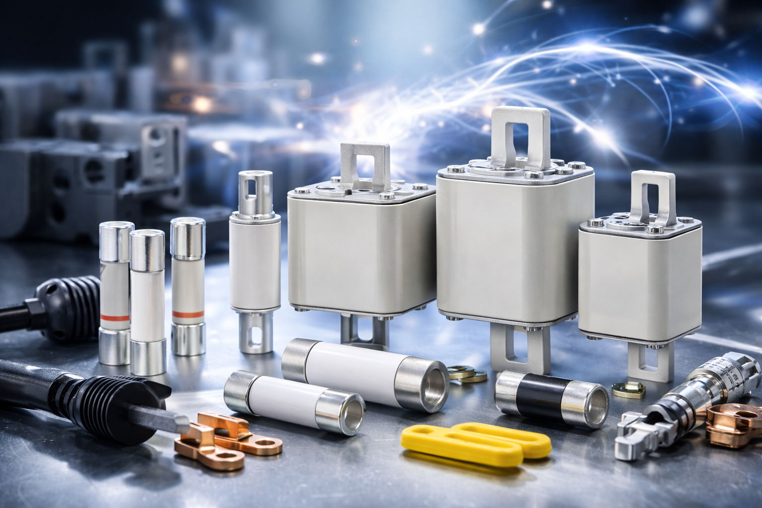
Eaton Bussmann Series Electrical Fuses – Blog & Fachwissen
Im Eaton Bussmann Series Electrical Fuses Blog finden Sie fundiertes Fachwissen rund um elektrische Sicherungen, Überstromschutz und moderne Schutzkonzepte für industrielle und gewerbliche Anwendungen. Diese Kategorie bündelt alle Blogartikel, technischen Beiträge und Praxisguides zu den Sicherungssystemen und Serien von Eaton Bussmann.
Eaton Bussmann zählt weltweit zu den führenden Herstellern von elektrischen Sicherungen, und ihre Serien stehen für Sicherheit, Normkonformität und höchste Zuverlässigkeit in anspruchsvollen elektrischen Systemen.
Was Sie im Eaton Bussmann Sicherungen Blog erwartet
Unsere Blogbeiträge helfen Ingenieuren, Einkäufern, Technikern und Planern dabei, die richtige Sicherungslösung zu finden und technische Zusammenhänge besser zu verstehen.
Themenschwerpunkte dieser Kategorie:
-
🔌 Überblick über Eaton Bussmann Sicherungsserien
-
⚙️ Unterschiede zwischen UL-, IEC- und Spezial-Sicherungen
-
📘 Technische Erklärungen zu Kennlinien, Auslöseverhalten & Bemessungswerten
-
🏭 Anwendungstipps für Industrie, Maschinenbau & Energieverteilung
-
🚗 Beiträge zu EV-, DC- und Hochvolt-Sicherungen
-
🛠 Best Practices für Auswahl, Installation und Wartung
Alle Inhalte sind praxisnah, verständlich aufbereitet und technisch fundiert.
Eaton Bussmann Sicherungsserien im Fokus
Der Blog behandelt regelmäßig verschiedene Eaton Bussmann Series Electrical Fuses, darunter:
-
Industrial Fuses
-
North American (UL) Fuse Series
-
IEC Sicherungsserien
-
High Speed & Semiconductor Fuses
-
EV & DC Sicherungen
-
Supplementary & Specialty Fuses
So erhalten Sie einen umfassenden Überblick über das Eaton Bussmann Portfolio und dessen Einsatzmöglichkeiten.
Fachwissen für sichere elektrische Systeme
Elektrische Sicherungen sind ein zentraler Bestandteil jeder sicheren Stromversorgung. Der Eaton Bussmann Series Electrical Fuses Blog unterstützt Sie dabei, Risiken zu minimieren, Normen einzuhalten und die Lebensdauer Ihrer Anlagen zu verlängern.
Ganz gleich, ob Sie Grundlagenwissen suchen oder tief in spezielle Sicherungsserien eintauchen möchten – hier finden Sie relevante, aktuelle und suchmaschinenoptimierte Inhalte rund um Eaton Bussmann Electrical Fuses.
👉 Jetzt Blogartikel entdecken und Ihr Wissen über Eaton Bussmann Sicherungsserien gezielt erweitern.
- Details
- Category: Electrical Fuses Blog
 eaton-bussmann-series-low-voltage-fuses-catalog-ca134002en-en-us.pdf  | [Eaton Bussmann Fuses] | 0 kB |
Eaton Bussmann Compatible Fuses – Original Quality and Reliable Alternatives
When it comes to electrical protection, choosing the right fuse is essential for ensuring the safety, reliability and performance of electrical systems. Eaton Bussmann fuses are widely recognised for their quality, reliability and dependable protection in industrial, commercial and electrical applications.
If you are looking for Eaton Bussmann compatible fuses, we recommend choosing original Eaton Bussmann products whenever possible. They are designed to meet demanding technical requirements and provide reliable protection for a wide range of electrical installations.
However, we understand that availability, delivery times and specific application requirements can influence purchasing decisions. That is why we can also offer other original fuse brands, including Lawson fuses, as alternative solutions.
Why Choose Original Eaton Bussmann Fuses?
Eaton Bussmann is an established manufacturer of electrical protection products, offering a comprehensive range of fuses for different applications.
Original Eaton Bussmann fuses offer several important advantages:
-
Reliable electrical protection: Designed to protect equipment and electrical circuits against overcurrents and short circuits.
-
Consistent product quality: Manufactured according to the relevant technical and quality standards.
-
Wide product range: Suitable for numerous industrial, commercial and electrical applications.
-
Technical compatibility: Original products are designed according to their specified electrical and mechanical characteristics.
-
Dependable performance: Help ensure the reliable operation of electrical systems when correctly selected and installed.
For these reasons, our first recommendation is always to use original Eaton Bussmann fuses when replacing existing components or maintaining electrical installations.
Eaton Bussmann Compatible Fuses – What Are the Alternatives?
Sometimes, the exact Eaton Bussmann fuse required may not be immediately available. In other cases, customers may be looking for alternative manufacturers offering original products with suitable technical specifications.
We can help you identify appropriate alternatives, depending on your application and requirements.
One of the original fuse brands we can offer is Lawson.
Lawson Fuses – An Alternative to Eaton Bussmann
Lawson fuses can be considered when looking for alternatives to specific Eaton Bussmann fuse types.
Depending on the product, Lawson fuses may provide a suitable option for applications where an equivalent fuse is required.
When selecting an alternative, it is important to compare the relevant technical specifications, including:
-
Rated voltage
-
Rated current
-
Breaking capacity
-
Fuse characteristics and operating class
-
Dimensions and mounting requirements
-
Applicable standards and approvals
Please note that compatible does not automatically mean interchangeable. Every replacement fuse should be checked against the original manufacturer's specifications and the requirements of the electrical application.
Our goal is to help you find a suitable original fuse product without compromising on safety or technical requirements.
Original Fuses from Established Manufacturers
Although Eaton Bussmann is our preferred recommendation for applications originally designed around Bussmann products, we can also supply original fuses from other manufacturers.
Depending on availability and technical requirements, we can help source suitable products from alternative manufacturers, including Lawson.
We focus on providing genuine products rather than unverified or imitation replacements. This gives customers greater confidence when sourcing replacement fuses for industrial equipment, electrical panels and other applications.
How to Find the Right Eaton Bussmann Replacement Fuse
Finding the correct replacement fuse is about more than matching the brand or product dimensions.
To identify the right fuse, we recommend checking the following information:
-
Original part number: The existing Eaton Bussmann reference is often the best starting point.
-
Electrical ratings: Check the rated voltage and current.
-
Fuse characteristics: Ensure the operating characteristics and breaking capacity meet the application requirements.
-
Physical dimensions: Verify that the replacement fits the existing fuse holder or installation.
-
Application requirements: Consider the equipment manufacturer's specifications and applicable electrical standards.
If you are unsure which product you need, providing the original part number or the technical details of your existing fuse can help us identify suitable options.
Our Recommendation: Original Eaton Bussmann or Original Lawson Fuses
Our recommendation is straightforward: whenever possible, choose original Eaton Bussmann fuses for applications designed around Eaton Bussmann products.
If the required Bussmann fuse is unavailable or you are looking for an alternative, we can also offer original Lawson fuses and other suitable original fuse products, subject to technical verification.
We believe that the right replacement should combine technical suitability, product authenticity and reliable availability.
Contact Us for Eaton Bussmann Compatible Fuses
Are you looking for Eaton Bussmann compatible fuses, an original Bussmann replacement or an alternative from Lawson?
We are happy to assist you in identifying the right product for your application.
Send us your Eaton Bussmann part number, product reference or technical specifications. We will check the available options and help you find a suitable original fuse.
Whether you need original Eaton Bussmann fuses or an alternative such as Lawson, we can help you find the right solution for your requirements.
- Details
- Category: Electrical Fuses Blog
| eaton-bussmann-series-high-speed-fuses-application-guide-br132015en-en-us.pdf | [Eaton Bussmann Fuses Technical Guide] | 0 kB |
How to Read Fuse Symbols and Markings: A Complete Guide
Introduction
Fuses are essential safety components in electrical and electronic systems. They protect circuits, equipment, and connected components from excessive current by interrupting the electrical flow when a fault occurs. However, selecting, identifying, or replacing a fuse requires more than simply checking its physical appearance.
Understanding how to read fuse symbols and markings is an important skill for electrical engineers, technicians, electricians, maintenance professionals, and anyone working with electrical protection systems.
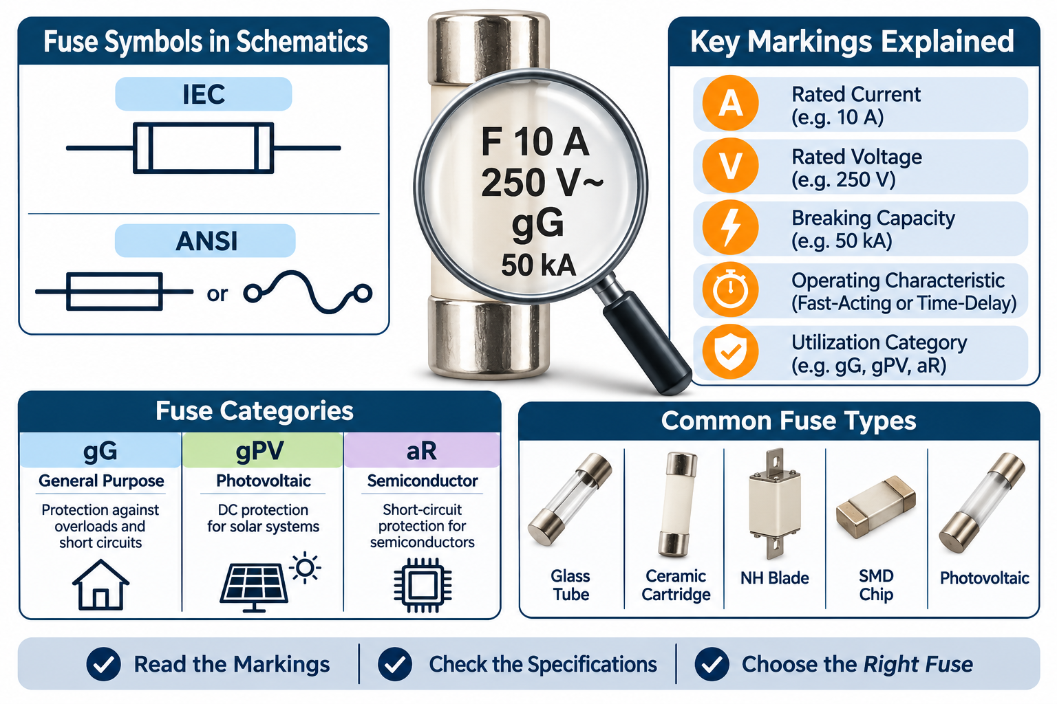
Fuse symbols on electrical schematics indicate where protective devices are installed, while the markings on physical fuses provide essential information about their operating characteristics, rated current, voltage, breaking capacity, and intended applications.
Misinterpreting these details can result in incorrect fuse selection, inadequate circuit protection, equipment damage, or electrical safety risks.
In this guide, we explain how to read fuse symbols and markings, understand common identification codes, distinguish between different fuse types, and match schematic specifications with the correct physical fuse.
1. What Are Fuse Symbols and Why Are They Important?
A fuse symbol is a standardized graphical representation used in electrical circuit diagrams and engineering schematics to identify the position of a fuse within a circuit.
It helps engineers and technicians understand where overcurrent protection is provided and how the protective device is incorporated into the electrical system.
Although different standards use slightly different graphical representations, the basic purpose remains the same: to indicate the presence and function of a fuse.
Understanding fuse symbols is important for several reasons:
-
Circuit identification: Helps locate protective devices within electrical schematics.
-
Electrical troubleshooting: Makes it easier to identify fuse positions when diagnosing circuit faults.
-
Component selection: Helps engineers determine the appropriate protective device for an application.
-
Maintenance and replacement: Reduces the risk of installing an incompatible replacement fuse.
-
Electrical safety: Supports correct protection against overloads and short circuits.
It is important to remember that a fuse symbol only identifies the protective function. The detailed electrical specifications must be obtained from the accompanying annotation, component list, or technical datasheet.
2. Understanding Common Fuse Symbols: IEC and ANSI Standards
Fuse symbols can vary depending on the electrical drafting standard used in a particular country or engineering project.
Two commonly encountered standards are IEC 60617 and ANSI/IEEE Y32.2.
IEC Fuse Symbol
Under IEC 60617, a fuse is generally represented by a rectangular symbol with internal vertical lines near the ends.
The connecting conductors meet the outer edges of the rectangle.
This graphical representation identifies the fuse's function without specifying its physical construction, size, or electrical rating.
IEC symbols are widely used in international electrical engineering documentation, industrial equipment drawings, and electrical control systems.
ANSI Fuse Symbol
ANSI/IEEE Y32.2 includes two commonly recognized fuse symbol representations:
-
A rectangular symbol with a continuous line through its centre.
-
An S-shaped curve with small terminal circles representing the fuse element.
The rectangular representation is frequently found in older North American electrical drawings, while the curved representation provides a more descriptive illustration of the fuse element.
IEC vs. ANSI Fuse Symbols
Although both standards represent the same protective function, their graphical conventions are not identical.
When interpreting electrical schematics, engineers should identify the drafting standard before making assumptions based on the symbol's appearance.
The reference designator also provides useful information:
-
F or FU: Common reference designators for fuses.
-
R: Typically identifies a resistor.
-
Q or CB: Commonly identifies a switching or circuit-breaker device, depending on the drafting convention.
Never rely exclusively on the graphical appearance of a symbol when the applicable drawing standard is unknown.
3. How to Read Fuse Markings on Electrical Schematics
The annotation beside a fuse symbol provides the electrical information needed to identify and specify the protective device.
A typical fuse annotation may include:
-
Reference designator.
-
Operating characteristic.
-
Rated current.
-
Rated voltage.
For example:
F1 T 1.6A 250V
This marking can be interpreted as follows:
-
F1: Identifies the first fuse in the electrical design.
-
T: Indicates a time-delay fuse.
-
1.6A: Specifies the rated current of 1.6 amperes.
-
250V: Indicates a rated voltage of 250 volts.
Understanding the difference between these markings is essential.
Reference Designator
The reference designator identifies a particular component within an electrical circuit.
For example, F1, F2, and F3 may identify three different fuses in the same schematic.
These labels help engineers locate components in circuit diagrams, bills of materials, and maintenance documentation.
The reference designator does not indicate the fuse's operating speed or electrical rating.
Fuse Operating Characteristics
Fuse operating characteristics describe how quickly a fuse responds when excessive current flows through it.
The two commonly used markings are:
-
F – Fast-Acting: Designed to interrupt excessive current quickly. These fuses are suitable for circuits containing components that require rapid overcurrent protection.
-
T – Time-Delay: Designed to tolerate temporary current surges without opening immediately. They are commonly used in circuits with motors, transformers, and other equipment that produces short-duration inrush currents.
Choosing the wrong operating characteristic can result in nuisance fuse operation or insufficient protection.
Rated Current
The current rating, measured in amperes (A), indicates the current a fuse is designed to carry under specified operating conditions.
Common examples include:
-
1A
-
2A
-
5A
-
10A
-
16A
-
32A
-
63A
A fuse's rated current should not be confused with its minimum melting current or its guaranteed operating threshold.
Its actual operating behaviour depends on factors such as current magnitude, duration, ambient temperature, and the fuse's time-current characteristics.
Rated Voltage
The voltage rating indicates the maximum circuit voltage for which the fuse is designed to operate safely under specified conditions.
Common markings include:
-
125V
-
250V
-
500V
-
690V
-
1000V DC
-
1500V DC
The voltage rating is particularly important because a fuse must be capable of safely extinguishing the electrical arc that develops when it interrupts a fault.
A fuse with an adequate current rating but an insufficient voltage rating may fail to interrupt the fault safely.
Always check whether the fuse is rated for AC or DC applications. AC and DC interruption characteristics are different, and a fuse must be suitable for the actual circuit conditions.
4. Understanding Fuse Utilization Categories: gG, gPV and aR
Utilization categories provide additional information about the intended operating conditions and protection capabilities of a fuse.
Under the IEC 60269 series of standards, utilization categories generally consist of two letters.
The first letter describes the fuse's breaking range, while the second identifies its intended application.
Understanding these classifications is especially important in industrial electrical systems, renewable energy installations, and semiconductor protection.
gG – General-Purpose Fuse
The gG utilization category identifies a full-range fuse designed for general-purpose protection.
These fuses provide protection against both overloads and short circuits.
Typical applications include:
-
Electrical distribution systems.
-
Cable and conductor protection.
-
Industrial control panels.
-
General low-voltage electrical installations.
The gG category is commonly used in conventional electrical distribution applications.
gPV – Photovoltaic Fuse
The gPV category is specifically designed for photovoltaic applications and is covered by IEC 60269-6.
Solar PV systems have particular electrical characteristics, including high DC operating voltages and specific fault-current conditions.
Photovoltaic fuses are designed to address the protection requirements of solar strings and arrays.
Typical applications include:
-
Solar panel strings.
-
PV combiner boxes.
-
Solar DC distribution systems.
-
Photovoltaic energy installations.
Using a correctly specified gPV fuse helps provide appropriate overcurrent protection in photovoltaic circuits.
aR – Semiconductor Protection Fuse
The aR utilization category identifies a partial-range fuse designed primarily for short-circuit protection of semiconductor devices.
These fuses are commonly used to protect sensitive electronic components such as:
-
Power semiconductor devices.
-
Thyristors.
-
Rectifiers.
-
Inverters.
-
Power conversion equipment.
Unlike full-range fuses, aR fuses are not intended to provide complete overload protection independently. Additional protection may be required to address overload conditions.
Understanding the Difference
| Fuse Category | Breaking Range | Typical Application |
|---|---|---|
| gG | Full-range | General electrical protection |
| gPV | Full-range | Photovoltaic systems |
| aR | Partial-range | Semiconductor short-circuit protection |
The utilization category should never be overlooked when selecting a replacement fuse. Two fuses with identical current and voltage ratings may have different operating characteristics and application requirements.
5. How to Read Markings on a Physical Fuse
Reading markings directly from a physical fuse is just as important as interpreting its schematic symbol.
Manufacturers typically print or engrave essential electrical specifications on the fuse body, end caps, or identification labels.
Depending on the fuse design and available marking space, these details may include:
Current Rating (A)
The current rating identifies the nominal current capacity of the fuse.
For example, a marking of 20A indicates a rated current of 20 amperes.
Voltage Rating (V)
The voltage marking indicates the rated operating voltage.
For example, 500V AC or 1000V DC identifies the voltage rating and current type for which the fuse is designed.
Breaking Capacity
Breaking capacity, also called interrupting rating, indicates the maximum prospective fault current that a fuse can safely interrupt under its specified test conditions.
It may be expressed in amperes or kiloamperes (kA).
For example, a marking of 50kA indicates a rated breaking capacity of 50,000 amperes under the applicable conditions.
This specification is critical because the prospective short-circuit current in an electrical installation must not exceed the fuse's rated breaking capacity.
Utilization Category
Markings such as gG, gPV, and aR identify the fuse's operating category and intended protection application.
These classifications help determine whether the fuse is appropriate for a particular electrical system.
AC or DC Identification
Physical fuse markings may also specify whether the device is intended for alternating-current (AC) or direct-current (DC) applications.
This distinction is particularly important in solar photovoltaic systems, battery storage installations, electric vehicles, and other DC power applications.
Manufacturer and Certification Information
Depending on the product, additional markings may identify:
-
Manufacturing specifications.
-
Applicable technical standards.
-
Certification or approval marks.
-
Product series or model numbers.
-
Manufacturing batch or traceability codes.
These markings help users verify product identity and check compliance with the relevant application requirements.
6. Common Physical Fuse Types and Their Identification
Fuse symbols do not identify the physical construction of a fuse. The same schematic symbol can represent several different fuse designs.
Physical fuse types are selected according to electrical ratings, installation requirements, breaking capacity, and application.
Common types include:
Glass Tube Fuses
Glass tube fuses feature a cylindrical glass body with metal end caps.
They allow visual inspection of the internal fuse element and are commonly found in electronic equipment and low-power electrical circuits.
Ceramic Cartridge Fuses
Ceramic cartridge fuses use a ceramic body instead of glass.
Their construction can provide greater mechanical strength and support higher electrical ratings and breaking capacities, depending on the design.
They are commonly used in industrial equipment and electrical distribution applications.
NH Blade Fuses
NH fuses are industrial low-voltage fuse links featuring a rectangular body and blade-type electrical contacts.
They are widely used in electrical distribution systems, industrial switchgear, and power protection installations.
SMD Chip Fuses
Surface-mount device (SMD) fuses are compact protective components designed for installation directly onto printed circuit boards.
They are commonly used in consumer electronics, communication equipment, and compact electronic devices.
Photovoltaic Fuses
Photovoltaic fuses are specifically designed for DC protection in solar energy systems.
They are available in different physical sizes and electrical ratings to accommodate various solar installation requirements.
The correct fuse must be selected according to the system voltage, rated current, breaking capacity, and applicable photovoltaic protection requirements.
7. Common Mistakes When Reading Fuse Symbols and Markings
Incorrect interpretation of fuse markings can lead to component mismatches and potentially dangerous electrical faults.
The following mistakes should be avoided.
Confusing F1 with the Fast-Acting Characteristic
F1 identifies a fuse's position in a circuit diagram. It does not automatically mean that the fuse has a fast-acting characteristic.
The separate F marking before a current rating indicates a fast-acting fuse.
Ignoring the Voltage Rating
Selecting a fuse based only on its current rating is insufficient.
The voltage rating must be appropriate for the circuit, and AC/DC compatibility must also be considered.
Overlooking Breaking Capacity
A fuse may have the correct current and voltage ratings but still be unsuitable if its breaking capacity is lower than the prospective short-circuit current.
Always verify the available fault current and the fuse's rated interrupting capability.
Confusing gG and gPV Fuses
Although these fuse categories may have similar physical appearances, they are designed for different protection applications.
A general-purpose fuse should not automatically be considered an acceptable replacement for a photovoltaic fuse.
Ignoring the Time-Current Characteristic
Replacing a time-delay fuse with a fast-acting fuse can result in unnecessary interruptions during normal starting or inrush conditions.
Similarly, installing a time-delay fuse where rapid protection is required may compromise circuit protection.
Selecting a Fuse Based Only on Physical Dimensions
Two fuses may have identical dimensions but completely different electrical specifications.
Always compare the full electrical and utilization specifications rather than relying on physical appearance alone.
8. Practical Checklist for Identifying and Selecting the Correct Fuse
Before installing or replacing a fuse, check the following specifications:
-
Reference designator: Confirm the fuse identification in the electrical schematic.
-
Operating characteristic: Determine whether a fast-acting or time-delay fuse is required.
-
Rated current: Verify the specified current rating and operating conditions.
-
Rated voltage: Confirm that the voltage rating is suitable for the actual AC or DC circuit.
-
Breaking capacity: Ensure that the fuse can safely interrupt the prospective fault current.
-
Utilization category: Check whether gG, gPV, aR, or another category is required.
-
Physical dimensions: Confirm compatibility with the fuse holder or installation.
-
Technical standards: Verify compliance with the relevant IEC or other applicable standards.
-
Technical datasheet: Cross-check the physical markings against the manufacturer's specifications.
-
Application requirements: Confirm that the fuse is suitable for the equipment and operating environment.
Following this checklist helps reduce component selection errors and improves the reliability of electrical protection systems.
9. Frequently Asked Questions About Fuse Symbols and Markings
What does F1 mean on a circuit diagram?
F1 is a reference designator identifying a specific fuse in an electrical circuit. It indicates the component's position in the design rather than its operating characteristic.
What is the difference between IEC and ANSI fuse symbols?
IEC 60617 generally represents a fuse using a rectangular symbol with internal vertical lines near the ends. ANSI/IEEE Y32.2 uses a rectangular symbol with a continuous centre line or an S-shaped curve with terminal circles.
Both represent the same protective function, but their graphical conventions differ.
What does T mean on a fuse?
T indicates a time-delay fuse. It is designed to withstand certain temporary current surges without opening immediately, making it suitable for applications with starting currents or inrush currents.
What does F mean on a fuse?
F indicates a fast-acting fuse. It is designed to respond quickly to excessive current and is commonly used where sensitive components require rapid overcurrent protection.
What does gG mean on a fuse?
gG identifies a full-range general-purpose fuse designed to provide both overload and short-circuit protection.
What does gPV mean on a fuse?
gPV identifies a full-range fuse specifically designed for photovoltaic applications, including solar string and array protection.
What does aR mean on a fuse?
aR identifies a partial-range fuse intended primarily for short-circuit protection of semiconductor devices. Additional protection is required for overload conditions where applicable.
Can the fuse symbol tell me the current and voltage rating?
No. The graphical symbol only indicates the presence and function of a fuse. Current and voltage ratings must be obtained from the schematic annotation, component specifications, physical markings, or technical datasheet.
Why is breaking capacity important when selecting a fuse?
Breaking capacity determines the maximum prospective fault current that a fuse can safely interrupt under specified conditions. An inadequate breaking capacity can result in dangerous failure during a short circuit.
Can two fuses with the same current rating be interchangeable?
Not necessarily. They may have different voltage ratings, breaking capacities, operating characteristics, utilization categories, or physical dimensions. All relevant specifications must be checked before replacement.
Conclusion
Understanding how to read fuse symbols and markings is essential for selecting, identifying, and maintaining the correct electrical protection devices.
Fuse symbols provide information about the position and function of protective devices in electrical schematics, while their annotations and physical markings communicate the specifications required for correct selection.
From current and voltage ratings to operating characteristics, breaking capacity, and utilization categories such as gG, gPV, and aR, every marking plays an important role in determining whether a fuse is suitable for its intended application.
For electrical engineers, technicians, and system designers, the most reliable approach is to evaluate the complete fuse specification rather than focusing on a single marking or physical feature.
By understanding the differences between IEC and ANSI symbols, correctly interpreting fuse annotations, and verifying physical fuse markings against technical datasheets, users can make more informed decisions and help ensure safe, reliable, and effective electrical circuit protection.

- Details
- Category: Electrical Fuses Blog
| eaton-bussmann-series-dc-fuses-catalog-ca135009en-us.pdf | [Eaton Bussmann DC Fuses] | 0 kB |
How Does a DC Fuse Protect Electrical Systems?
Introduction
Electrical systems rely on effective protection devices to maintain safe and reliable operation. In direct current (DC) applications, a sudden increase in current, an overload, or a short circuit can cause serious damage to electrical components, wiring, and connected equipment. Without proper protection, excessive current may lead to overheating, equipment failure, fire hazards, and costly system downtime.
A DC fuse is an essential electrical protection component designed to prevent these problems. It protects electrical circuits by interrupting the flow of current when it exceeds a predetermined safe limit. Although its operating principle may appear simple, the process involves thermal energy, specially designed fuse elements, and advanced arc-extinguishing technology.
But how does a DC fuse protect electrical systems, and why is it important in modern electrical applications?
This article explains the working principle of a DC fuse, its protection mechanisms, its role in preventing electrical faults, and the key factors to consider when selecting the right fuse.
1. What Is a DC Fuse?
A DC fuse is an electrical safety device designed to protect direct current circuits from excessive current caused by overloads or short circuits.
It typically consists of a specially designed conductive element enclosed within an insulating housing. Under normal operating conditions, electrical current flows through the fuse element without interruption. However, when the current exceeds the fuse's rated capacity for a sufficient period, the element heats up and eventually melts, opening the circuit.
This interruption prevents excessive electrical energy from reaching sensitive components and helps reduce the risk of equipment damage.
DC fuses are commonly used in:
-
Solar photovoltaic (PV) systems
-
Battery energy storage systems
-
Electric vehicles and charging infrastructure
-
Industrial DC power distribution
-
Telecommunications equipment
-
DC power supplies and control systems
Unlike ordinary connecting components, a DC fuse is specifically engineered to interrupt fault currents safely, including the electrical arc that develops when its element melts.
2. How Does a DC Fuse Work?
The working principle of a DC fuse is based on the heating effect of electric current. When current passes through the fuse element, electrical resistance generates heat. Under normal conditions, this heat is dissipated into the surrounding materials and environment.
When excessive current flows through the circuit, heat generation increases. Once the fuse element reaches its designed melting temperature, it melts and disconnects the electrical circuit.
The protection process involves several important stages.
Step 1: Normal Current Flow
During normal operation, the DC fuse allows current to pass through its conductive element.
The element has a carefully calculated cross-sectional area and electrical resistance. These characteristics ensure that it can carry the expected operating current without reaching its melting temperature.
Heat generated inside the fuse is transferred to the surrounding filler material and housing, allowing the fuse to maintain a stable operating temperature.
Step 2: Excessive Current Generates Heat
When an overload or short circuit occurs, the current increases beyond the normal operating level.
According to Joule's law, the heat generated by an electrical conductor depends on its resistance, current, and operating time.
The relationship can be expressed as:
Q = I²Rt
Where:
-
Q = Heat energy generated
-
I = Current flowing through the fuse
-
R = Electrical resistance
-
t = Time
Because heat generation increases with the square of the current, even a relatively small increase in current can significantly increase the thermal stress on the fuse element.
Step 3: The Fuse Element Melts
DC fuse elements are carefully engineered with narrow sections, often called constrictions or necks.
These sections have a smaller cross-sectional area, resulting in higher current density and concentrated heat generation.
When the temperature exceeds the designed limit, the narrow sections melt or vaporize, depending on the magnitude of the fault current.
This creates a break in the conductive path and begins the electrical interruption process.
Step 4: The Electrical Arc Is Extinguished
When the fuse element melts, an electrical arc may form across the resulting gap.
Arc extinction is particularly important in DC systems because direct current does not naturally pass through zero, unlike alternating current (AC).
To interrupt DC current safely, the fuse must generate sufficient arc voltage to force the current down to zero.
Many high-breaking-capacity DC fuses contain quartz sand or another suitable arc-quenching filler. During a short-circuit event, this material helps absorb heat, contain the arc, and form a glass-like structure around the interruption zone.
This process increases arc resistance and helps extinguish the electrical arc safely.
Step 5: The Circuit Is Disconnected
Once the arc is extinguished, the conductive path remains open.
Current can no longer flow through the fuse, isolating the protected circuit from the fault.
The fuse must then be inspected and replaced with an appropriate replacement before the system is returned to service.
3. How Does a DC Fuse Protect Against Electrical Faults?
A DC fuse provides protection against two major types of electrical faults: overloads and short circuits.
Although both conditions involve excessive current, their characteristics and the way a fuse responds are different.
Overload Protection
An overload occurs when electrical equipment draws more current than the circuit is designed to carry during normal operation.
Common causes include:
-
Excessive electrical loads
-
Equipment malfunction
-
Incorrect system configuration
-
Overloaded battery circuits
-
Changes in operating conditions
During an overload, the fuse element heats up gradually. If the excessive current continues for long enough, the element reaches its melting temperature and opens the circuit.
This prevents prolonged overheating of conductors and electrical components.
The time required for the fuse to operate depends on the magnitude of the overload, ambient temperature, heat dissipation, and the fuse's time-current characteristics.
Short-Circuit Protection
A short circuit occurs when an unintended low-resistance connection creates a direct current path between electrical conductors or between a conductor and ground.
This can produce an extremely high fault current within a very short period.
A DC fuse responds by rapidly melting or vaporizing its specially designed element. The resulting arc is controlled and extinguished inside the fuse.
Current-limiting DC fuses can interrupt fault current before it reaches its potential peak, reducing the electrical energy delivered to the protected equipment.
This helps protect:
-
Electrical cables and conductors
-
Battery systems
-
Power conversion equipment
-
Semiconductor devices
-
Electrical distribution components
Effective short-circuit protection depends on selecting a fuse with an appropriate voltage rating and sufficient interrupting capacity for the available fault current.
4. Why Is Arc Extinction Important in DC Fuse Protection?
Arc extinction is one of the most important characteristics of DC fuse technology.
In AC electrical systems, current naturally crosses zero during every cycle. This provides an opportunity for an electrical arc to extinguish.
DC systems operate differently. Their current flows continuously in one direction and does not have a natural zero-crossing point.
As a result, an electrical arc can continue even after the fuse element melts.
If the arc is not extinguished effectively, it may cause:
-
Excessive heat generation
-
Damage to the fuse housing
-
Metal vapor deposition
-
Internal pressure buildup
-
Equipment damage and potential safety hazards
To address this challenge, DC fuses use specialized element geometries, insulating housings, and arc-quenching materials.
Their design helps generate sufficient arc voltage to interrupt current and contain the energy released during a fault.
This is also why a fuse's DC voltage rating is critical. A fuse designed for a particular DC voltage must not automatically be assumed suitable for a higher-voltage application.
5. What Role Does Quartz Sand Play in a DC Fuse?
Quartz sand is commonly used as an arc-quenching filler in high-breaking-capacity fuses.
It performs several important functions throughout the fuse's operating process.
Heat dissipation: During normal operation, the filler helps transfer heat away from the fuse element, supporting thermal stability.
Arc containment: When the fuse element melts, the filler helps contain the electrical arc within the fuse body.
Arc quenching: Under short-circuit conditions, the intense heat can melt surrounding quartz particles into a glass-like structure. This helps increase resistance within the arc path and supports rapid current interruption.
Improved safety: By controlling the arc and containing the energy released during interruption, the filler helps prevent damage to surrounding electrical components.
The combination of the fuse element, housing, and filler material is essential to achieving reliable DC fault interruption.
6. What Are the Main Benefits of Using a DC Fuse?
DC fuses provide several important advantages for electrical protection systems.
1. Protection Against Overloads
A properly selected DC fuse interrupts excessive current before prolonged overheating causes damage to electrical equipment and conductors.
2. Fast Short-Circuit Interruption
Current-limiting fuses can respond rapidly to high fault currents, reducing the amount of electrical energy that reaches protected components.
3. Protection of Sensitive Equipment
DC systems frequently contain sensitive electronic components, including power semiconductors, converters, and battery management equipment.
Appropriate fuse selection helps limit fault energy and reduce the risk of expensive component failures.
4. Improved Electrical Safety
By interrupting dangerous fault currents and containing electrical arcs, DC fuses contribute to safer electrical installations.
5. Simple and Reliable Operation
A conventional fuse does not require an external control signal or complicated operating mechanism to respond to excessive current.
Its operation is based on the physical properties of the fuse element and its internal construction.
6. Compact Protection Design
DC fuses are available in different sizes, current ratings, and configurations, making them suitable for a wide range of electrical applications.
7. How to Choose the Right DC Fuse for an Electrical System
Selecting the correct DC fuse is essential for achieving reliable protection. Choosing a fuse based only on its current rating is not sufficient.
Several electrical and environmental parameters must be considered.
Rated Voltage
The fuse's rated DC voltage must be equal to or higher than the maximum system voltage under the relevant operating conditions.
The DC voltage rating is particularly important because the fuse must be capable of extinguishing the arc after the element melts.
Rated Current
The fuse's rated current should be selected according to the normal operating current, conductor capacity, equipment requirements, and applicable design standards.
The selection should also account for ambient temperature and installation conditions.
Breaking Capacity
Breaking capacity refers to the maximum prospective fault current that a fuse can safely interrupt at its specified voltage and under its rated conditions.
The selected fuse must have a breaking capacity greater than or equal to the maximum available short-circuit current at its installation point.
Time-Current Characteristics
Time-current characteristics indicate how quickly a fuse operates at different current levels.
They are important for distinguishing between temporary current variations, sustained overloads, and high-current short circuits.
I²t Value
The I²t value represents the thermal energy associated with current flowing through the fuse during its operating and interruption process.
It is especially important when protecting sensitive semiconductor devices.
The total clearing I²t of the fuse should be coordinated with the withstand capability of the protected equipment.
Environmental Conditions
Ambient temperature, ventilation, enclosure design, and terminal connection quality can influence fuse performance.
These factors should be considered during fuse selection and installation.
8. Where Are DC Fuses Commonly Used?
DC fuses are essential in many modern electrical applications where reliable direct current protection is required.
Solar Photovoltaic Systems
Solar PV installations use DC fuses to protect photovoltaic strings, combiner boxes, and other DC circuit components.
They help interrupt excessive currents caused by faults, including reverse current from parallel-connected strings.
Battery Energy Storage Systems
Battery energy storage systems can deliver substantial fault currents, making effective overcurrent protection particularly important.
DC fuses help protect battery circuits, power distribution connections, and associated electrical equipment against overloads and short circuits.
Electric Vehicles
Electric vehicles use high-voltage DC electrical systems to supply power to electric motors and other components.
Specialized DC fuses help protect battery circuits, power electronics, and high-voltage distribution systems.
Industrial DC Applications
Industrial facilities use DC power for automation, control systems, power supplies, and specialized machinery.
Appropriately selected DC fuses help protect electrical equipment and minimize the consequences of unexpected faults.
Telecommunications Systems
Telecommunications infrastructure often relies on DC power distribution to maintain continuous operation.
DC fuses provide overcurrent protection for power supplies, distribution panels, and backup battery systems.
9. DC Fuse vs. DC Circuit Breaker: What Is the Difference?
Both DC fuses and DC circuit breakers protect electrical systems against excessive current. However, they use different operating mechanisms.
| Feature | DC Fuse | DC Circuit Breaker |
|---|---|---|
| Operating principle | Melts a conductive element | Opens electrical contacts |
| Fault response | Depends on fuse characteristics | Depends on breaker design and trip characteristics |
| Reset capability | Must be replaced after operation | Can generally be reset |
| Maintenance | Requires replacement after operation | Requires inspection and resetting where appropriate |
| Current limitation | Can provide very fast current limitation | Depends on the breaker's design |
| Application | Overcurrent and short-circuit protection | Overcurrent and short-circuit protection |
A DC fuse is often preferred when fast current limitation, high breaking capacity, and compact protection are important.
A DC circuit breaker may be more convenient when resetting and switching operations are required.
The final choice depends on the electrical system, available fault current, protection coordination, maintenance requirements, and applicable standards.
10. Common Reasons a DC Fuse May Fail to Provide Proper Protection
Even a correctly designed fuse may not provide effective protection if it is incorrectly selected, installed, or coordinated with other electrical devices.
Common issues include:
Incorrect voltage rating: A fuse with an insufficient DC voltage rating may be unable to extinguish the arc safely.
Insufficient breaking capacity: If the prospective fault current exceeds the fuse's rated interrupting capacity, safe interruption cannot be assured.
Incorrect current rating: An oversized fuse may not provide adequate protection, while an undersized fuse may operate unnecessarily during normal operating conditions.
Poor electrical connections: Loose terminals and increased contact resistance can create localized overheating.
High ambient temperature: Excessive surrounding temperature can affect the fuse's thermal performance and cause premature operation.
Improper protection coordination: If upstream and downstream protective devices are not properly coordinated, the wrong fuse may operate during a fault.
To avoid these problems, engineers should evaluate the entire protection system rather than considering the fuse as an isolated component.
Frequently Asked Questions (FAQs)
1. How does a DC fuse protect an electrical circuit?
A DC fuse protects an electrical circuit by interrupting current when it exceeds a predetermined level for a sufficient period. Excessive current heats the fuse element until it melts, opening the circuit and isolating the fault.
2. Can a DC fuse protect against both overloads and short circuits?
Yes. A properly selected DC fuse can protect against both conditions. It responds to sustained overloads through gradual heating and melting, while high short-circuit currents cause rapid element vaporization and current-limiting interruption.
3. Why is a DC fuse different from an AC fuse?
The main difference is the arc-interruption requirement. DC current does not naturally cross zero, so a DC fuse must be designed to extinguish the electrical arc under its specified DC voltage and fault conditions.
4. Why is quartz sand used inside DC fuses?
Quartz sand helps dissipate heat, contain electrical arcs, and support arc extinction. Under high-temperature fault conditions, it can melt into a glass-like material that helps increase resistance within the arc path.
5. What happens when a DC fuse blows?
When a DC fuse operates, its conductive element melts or vaporizes, interrupting the current path. Once the arc is extinguished, the circuit remains open until the fuse is replaced and the underlying fault has been investigated and corrected.
6. How do I select the correct DC fuse rating?
Consider the system's maximum DC voltage, normal operating current, maximum prospective short-circuit current, breaking capacity, time-current characteristics, I²t requirements, and environmental conditions. The fuse must also be coordinated with the equipment and other protective devices.
7. Can a DC fuse protect sensitive electronic components?
Yes. A properly coordinated current-limiting DC fuse can help protect sensitive electronic equipment, including inverters and semiconductor devices. Its total clearing I²t must be compatible with the withstand capability of the protected components.
8. Is a DC fuse reusable?
No. A conventional DC fuse is a one-time protective device. Once its element melts and interrupts the circuit, the fuse must be replaced with a suitable equivalent after the cause of the fault has been identified.
Conclusion
A DC fuse plays a vital role in protecting electrical systems against overloads and short circuits. Its operation involves more than simply melting a conductive element. It relies on carefully controlled thermal behavior, specialized fuse element geometry, current limitation, and effective arc extinction.
By interrupting excessive current before it causes significant damage, a properly selected DC fuse helps protect electrical equipment, improve system safety, and maintain reliable operation.
However, effective DC fuse protection depends on selecting the correct voltage and current ratings, ensuring adequate breaking capacity, considering I²t requirements, and coordinating the fuse with the entire electrical system.
Whether used in solar photovoltaic installations, battery energy storage systems, electric vehicles, or industrial DC applications, choosing the appropriate DC fuse is an essential part of designing a safe and dependable electrical protection system.
- Details
- Category: Electrical Fuses Blog
| eaton-bussmann-series-dc-fuses-catalog-ca135009en-us.pdf | [Eaton Bussmann BESS Fuses] | 0 kB |
| HSF_Battery-Storage-Application-Guide_June-2020.pdf | [Eaton Bussmann BESS Fuses Application Guide] | 0 kB |
Common BESS Protection Failures: How to Diagnose and Prevent Them
Introduction
Battery Energy Storage Systems (BESS) play an increasingly important role in modern energy infrastructure. From renewable energy integration and grid stabilisation to commercial and industrial power management, these systems require reliable electrical protection to ensure safe, efficient, and uninterrupted operation.
However, even well-designed battery energy storage systems can experience protection failures. Unexpected fuse operation, overheating, incorrect fault isolation, DC arc interruption problems, and premature component degradation can compromise system performance and increase maintenance costs.
Understanding the common causes of BESS protection failures is essential for engineers, system integrators, facility operators, and maintenance professionals. Early diagnosis helps prevent equipment damage, reduce downtime, and improve the overall reliability of energy storage installations.
This article explores five common BESS protection failures, explains how to identify their root causes, and provides practical strategies to prevent them.
Why Is Electrical Protection Critical in Battery Energy Storage Systems?
Battery energy storage systems present unique electrical protection challenges compared with conventional power distribution systems.
Several factors make protection design particularly demanding:
-
High fault current: Multiple battery racks connected in parallel can deliver extremely high short-circuit currents.
-
High DC voltage: Modern utility-scale BESS installations commonly operate at 1000V DC or 1500V DC.
-
Elevated operating temperatures: Temperatures inside battery enclosures can reach 60°C or higher.
-
Frequent charge and discharge cycles: Repeated current fluctuations and thermal cycling place additional stress on protection components.
-
Complex protection architecture: Battery modules, racks, DC busbars, and power conversion systems require coordinated protection.
These conditions mean that selecting a fuse or circuit protection device based solely on its rated current is insufficient. Engineers must also consider operating temperature, DC voltage, breaking capacity, thermal characteristics, and protection coordination.
A protection device that is suitable under laboratory conditions may not deliver reliable performance in the actual operating environment.
1. Nuisance Tripping Under Normal Operating Conditions
One of the most common BESS protection problems is unexpected fuse operation during normal charging or discharging.
Nuisance tripping occurs when a fuse interrupts the circuit even though no genuine electrical fault has occurred. This can cause unnecessary system shutdowns, reduce energy availability, and increase maintenance requirements.
Common Causes
Incorrect fuse current rating
A fuse selected too close to the system's continuous operating current may not provide sufficient operating margin.
For example, a fuse rated at 100A under reference conditions may have a lower permissible continuous current when exposed to elevated ambient temperatures.
Insufficient temperature derating
High temperatures inside battery enclosures affect the current-carrying capability of electrical protection components.
A fuse operating at 60°C may have a significantly lower effective current capacity than the same fuse operating at 25°C.
Frequent charge and discharge cycles
Repeated charging and discharging can create thermal cycling within the fuse element. If switching frequency is not considered during fuse selection, premature operation may occur.
How to Diagnose Nuisance Tripping
Engineers should investigate the following parameters:
-
Measure the actual continuous operating current.
-
Check the ambient temperature around the fuse.
-
Compare the operating current with the temperature-derated fuse capacity.
-
Review charging and discharging frequency.
-
Verify whether all applicable derating factors were included during initial selection.
If the effective current-carrying capacity is lower than the system's maximum continuous operating current, the fuse selection should be reassessed.
How to Prevent It
To reduce nuisance tripping:
-
Select fuses with sufficient current-carrying capacity.
-
Apply temperature derating during the design stage.
-
Consider frequent charge and discharge cycles.
-
Evaluate enclosure ventilation and cooling conditions.
-
Verify fuse performance under actual operating conditions.
Correct fuse sizing is essential for maintaining reliable BESS operation.
2. Fuse Overheating Without Operation
A fuse that becomes excessively hot without interrupting the circuit is another important warning sign.
Although the fuse may continue carrying current, elevated temperatures can accelerate component degradation and damage surrounding electrical connections.
In severe cases, overheating can result in terminal damage, insulation deterioration, or unexpected system shutdown.
Common Causes
Loose terminal connections
Loose electrical connections increase contact resistance. Higher resistance generates additional heat when current flows through the connection.
This can create a cycle in which increasing temperature causes further connection deterioration.
Poor electrical contact
Oxidation, corrosion, contamination, or damaged contact surfaces can increase resistance between the fuse and its holder.
Underrated fuse holders
A fuse holder with an insufficient current rating may overheat even when the installed fuse is correctly selected.
The fuse and its holder must be compatible in terms of current rating, temperature performance, and installation requirements.
How to Diagnose Fuse Overheating
Thermal inspection is one of the most effective diagnostic methods.
Maintenance professionals should:
-
Use an infrared thermometer or thermal imaging camera.
-
Measure the temperature of the fuse body.
-
Inspect fuse holder contacts and terminal connections.
-
Compare temperatures between similar fuses carrying comparable loads.
-
Check terminal tightness against the specified installation torque.
-
Inspect for oxidation, corrosion, discoloration, or damaged contact surfaces.
A temperature rise exceeding 40 K above ambient should be treated as a warning requiring investigation, while actual acceptance limits must follow the component manufacturer's specifications.
How to Prevent It
Preventive measures include:
-
Using correctly rated fuse holders.
-
Ensuring proper terminal installation and tightening.
-
Maintaining clean electrical contact surfaces.
-
Performing periodic thermal inspections.
-
Replacing damaged or degraded connections.
-
Ensuring adequate ventilation inside electrical enclosures.
Importantly, replacing an overheated fuse without investigating the underlying connection problem may allow the same failure to happen again.
3. Protection Coordination Failure
Protection coordination is essential in battery energy storage systems because multiple protection devices operate at different levels.
A typical BESS protection architecture may include:
-
Battery module fuses.
-
Battery rack fuses.
-
DC bus protection.
-
Power conversion system (PCS) input protection.
Each protection device must operate appropriately according to the location and characteristics of an electrical fault.
What Happens During a Coordination Failure?
A coordination failure occurs when the wrong protection device operates during a fault.
For example, if a fault occurs within one battery rack but an upstream DC bus fuse operates first, multiple healthy battery racks may also become disconnected.
This can result in:
-
Unnecessary system-wide shutdowns.
-
Reduced energy availability.
-
Increased equipment damage.
-
Longer troubleshooting and recovery times.
-
Higher maintenance costs.
In another scenario, a downstream protection device may operate too slowly, allowing excessive fault energy to reach connected equipment.
Common Causes
Incorrect coordination study
Protection coordination studies must consider the actual electrical characteristics of the complete system.
Assuming a fixed fault current without accounting for different battery rack configurations can lead to incorrect protection settings or fuse selection.
Changes in battery rack configuration
The available fault current can vary depending on the number of battery racks connected and operating simultaneously.
If the actual configuration differs from the original design assumptions, protection coordination margins may change.
Incompatible time-current characteristics
Upstream and downstream fuses must have appropriately coordinated time-current characteristics to achieve selective fault isolation where required.
How to Diagnose Coordination Problems
When investigating a coordination failure:
-
Identify which protection device operated.
-
Determine the actual location of the electrical fault.
-
Compare the operated protection device with the intended protection level.
-
Review the system's actual battery rack configuration.
-
Reassess the time-current characteristics of upstream and downstream protection devices.
-
Verify coordination across the expected fault current range.
How to Prevent It
Reliable protection coordination requires:
-
Performing a detailed protection coordination study.
-
Considering minimum and maximum available fault currents.
-
Accounting for different battery rack operating configurations.
-
Verifying time-current characteristics.
-
Reviewing protection coordination whenever the system configuration changes.
Proper coordination helps isolate electrical faults without unnecessarily disconnecting healthy parts of the energy storage system.
4. DC Arc Interruption Failure
DC arc interruption failure is one of the most serious electrical protection problems in BESS applications.
Unlike AC systems, DC systems do not have a natural current zero-crossing that helps extinguish an electrical arc.
As a result, interrupting a DC fault requires protection devices specifically designed and rated for the electrical conditions involved.
Common Causes
Incorrect DC voltage rating
Using a fuse with an insufficient DC voltage rating can prevent reliable interruption of a fault.
A fuse suitable for an AC application or a lower-voltage DC system should not automatically be considered suitable for a high-voltage battery energy storage installation.
The fuse must have an appropriate DC voltage rating for the maximum system voltage.
Insufficient breaking capacity
The fuse must be capable of safely interrupting the maximum prospective short-circuit current available at its installation point.
If its breaking capacity is insufficient, safe fault interruption cannot be guaranteed.
Incompatible system time constant
The electrical time constant, expressed as L/R, influences the behaviour of DC fault current.
If the actual system time constant exceeds the value for which the fuse is rated, the fuse may not interrupt the fault as intended.
How to Diagnose DC Arc Interruption Problems
Engineers should review:
-
The fuse's rated DC voltage.
-
Maximum system operating voltage.
-
Prospective short-circuit current.
-
Fuse breaking capacity.
-
System L/R time constant.
-
Evidence of incomplete arc interruption.
Physical signs that may indicate an interruption problem include:
-
Cracked fuse bodies.
-
Blackened or damaged contact areas.
-
Visible pitting.
-
Signs of sustained arcing.
-
Damage to nearby components.
Any suspected DC interruption failure requires immediate attention from qualified electrical personnel. The affected circuit should remain isolated until its safety has been established.
How to Prevent It
To improve DC fault interruption reliability:
-
Select protection devices specifically rated for the intended DC application.
-
Verify rated voltage against maximum system voltage.
-
Ensure breaking capacity exceeds the prospective fault current.
-
Check compatibility with the system time constant.
-
Follow the protection device manufacturer's application requirements.
-
Validate the complete protection design before commissioning.
Correct DC fuse selection is particularly important in high-voltage energy storage installations.
5. Premature Fuse Aging and Degradation
A fuse can experience premature aging even when its initial current and voltage ratings appear suitable.
Over time, continuous exposure to elevated temperatures and repeated thermal cycling can affect the physical characteristics of the fuse element.
This may change its operating characteristics and increase the likelihood of unexpected interruption.
Common Causes
Continuous high-temperature operation
Elevated ambient temperatures accelerate material degradation and can affect the long-term stability of the fuse element.
Battery enclosures operating at temperatures of 60°C or higher may create challenging thermal conditions for electrical protection components.
Repeated thermal cycling
Frequent battery charging and discharging cause temperature variations within electrical components.
Repeated expansion and contraction can contribute to mechanical stress and degradation over extended operating periods.
Poor thermal management
Insufficient ventilation, inadequate cooling, and poorly designed enclosure layouts can expose protection components to excessive temperatures.
How to Diagnose Premature Aging
Maintenance professionals should:
-
Review the operating history of failed fuses.
-
Compare actual service life with expected service life.
-
Examine operating temperature records.
-
Review charge and discharge frequency.
-
Inspect for discoloration and other visible signs of degradation.
-
Investigate whether similar components are experiencing comparable failures.
If several fuses in the same installation show premature degradation, the underlying thermal environment should be investigated rather than simply replacing individual components.
How to Prevent Premature Aging
Recommended preventive measures include:
-
Selecting components with appropriate temperature ratings.
-
Applying all relevant derating factors.
-
Improving enclosure ventilation.
-
Maintaining effective thermal management.
-
Monitoring temperature during normal operation.
-
Including thermal inspections in preventive maintenance schedules.
Managing temperature is essential for extending the service life of BESS electrical protection components.
6. Practical BESS Protection Failure Diagnostic Checklist
A systematic diagnostic process helps engineers identify the root cause of protection failures instead of relying on repeated component replacement.
The following checklist can be used when investigating fuse-related problems in battery energy storage systems.
Initial Failure Assessment
-
Identify the protection device that operated.
-
Record its location within the BESS.
-
Determine whether operation occurred during normal operation or an actual electrical fault.
-
Review the system's operating conditions before the event.
-
Check available fault records and monitoring data.
Electrical Parameter Verification
-
Verify the fuse's rated DC voltage.
-
Check the continuous operating current.
-
Confirm current rating after all applicable derating factors.
-
Verify the prospective short-circuit current.
-
Confirm that breaking capacity is adequate.
-
Review the system time constant where applicable.
-
Reassess protection coordination.
Thermal and Mechanical Inspection
-
Measure ambient temperature around the fuse.
-
Perform thermal imaging of fuse bodies and connections.
-
Compare temperatures across similar components.
-
Inspect fuse holders for damage.
-
Check for oxidation and corrosion.
-
Verify terminal torque against manufacturer specifications.
-
Look for discoloration, cracks, or signs of arcing.
Maintenance and Documentation
-
Record inspection findings.
-
Compare failure patterns across battery racks.
-
Review previous maintenance records.
-
Document replaced components.
-
Investigate recurring failures.
-
Update maintenance procedures when necessary.
Safety note: BESS systems can contain hazardous DC voltages and extremely high available fault currents. Electrical inspections, testing, isolation, and component replacement must be performed by qualified personnel following approved safety procedures. Do not handle, remove, or test suspected failed protection devices while the circuit remains energised.
7. Best Practices to Prevent BESS Protection Failures
Although individual failure modes have different causes, several design and maintenance practices can significantly improve overall protection reliability.
1. Select Fuses According to Actual Operating Conditions
Fuse selection should consider more than nominal current and voltage.
Engineers should evaluate:
-
Maximum continuous current.
-
Maximum DC operating voltage.
-
Ambient temperature.
-
Switching frequency.
-
Prospective short-circuit current.
-
Required breaking capacity.
-
System time constant.
-
Installation and cooling conditions.
2. Apply Appropriate Derating Factors
Temperature, thermal environment, and operating cycles can influence fuse performance.
All applicable derating factors should be considered during the design and selection process.
This helps ensure that the selected fuse operates within its intended performance range.
3. Verify Protection Coordination
A properly coordinated protection architecture helps ensure that faults are isolated at the appropriate level.
Coordination studies should account for different operating configurations, including variations in the number of battery racks connected.
4. Maintain Compatible Fuse Holders and Connections
The fuse holder is an important part of the protection system.
Its electrical and thermal ratings must be compatible with the installed fuse and the operating environment.
Proper installation, terminal tightening, and contact condition should also be verified.
5. Implement Regular Thermal Inspections
Thermal inspections can identify abnormal heating before it develops into a more serious failure.
A visual inspection and thermal check at least every six months can serve as a starting point for a preventive maintenance programme. Actual inspection intervals should be determined by operating conditions, risk assessments, manufacturer recommendations, and applicable standards.
6. Review Protection Design After System Modifications
Changes to battery capacity, rack configuration, power conversion equipment, or DC distribution can affect fault current and protection coordination.
Any significant modification should trigger a review of the protection design.
Frequently Asked Questions (FAQs)
1. What are the most common BESS protection failures?
The five most common fuse-related protection failures are nuisance tripping, fuse overheating without operation, protection coordination failure, DC arc interruption failure, and premature fuse aging.
These problems are commonly associated with incorrect fuse selection, inadequate temperature derating, poor electrical connections, insufficient breaking capacity, and unsuitable operating conditions.
2. Why does a BESS fuse trip during normal operation?
A BESS fuse may operate during normal charging or discharging when its effective current-carrying capacity is insufficient for the actual operating conditions.
Common causes include inadequate temperature derating, undersized fuse ratings, and frequent charge and discharge cycles.
3. Why does a battery energy storage fuse become hot without blowing?
Excessive heating without fuse operation often indicates increased electrical resistance at terminal connections or fuse holder contacts.
Loose connections, oxidation, corrosion, and undersized fuse holders can all contribute to overheating.
Thermal inspection and connection checks can help identify the underlying problem.
4. What is protection coordination in a BESS?
Protection coordination is the process of ensuring that electrical protection devices operate in an appropriate sequence during a fault.
The objective is to isolate the affected circuit while maintaining the operation of healthy parts of the battery energy storage system wherever possible.
5. Why are DC-rated fuses important in battery energy storage systems?
DC-rated fuses are designed and tested for the specific electrical interruption requirements of DC applications.
Because DC circuits do not have a natural current zero-crossing, the protection device must be capable of extinguishing the arc under the specified fault conditions.
Using an unsuitable fuse can compromise fault interruption and equipment safety.
6. How often should BESS fuses be inspected?
A visual inspection and thermal assessment at least every six months can provide a useful baseline for BESS preventive maintenance.
However, the appropriate frequency depends on operating temperature, cycling frequency, installation conditions, maintenance history, and manufacturer recommendations.
7. Can a correctly rated fuse still fail prematurely?
Yes. Even a correctly selected fuse can experience premature degradation when exposed to excessive temperatures, repeated thermal cycling, poor connections, or operating conditions outside its specified limits.
Correct initial selection must therefore be supported by appropriate installation and ongoing maintenance.
8. What should engineers check first when a BESS fuse fails?
The first step is to establish whether the fuse operated during a genuine electrical fault or under normal operating conditions.
Engineers should then investigate the fuse's voltage rating, current rating, derating factors, breaking capacity, connection condition, and protection coordination.
Understanding the failure circumstances helps identify the root cause and avoid repeated failures.
Conclusion
Reliable electrical protection is fundamental to the safety, availability, and long-term performance of battery energy storage systems.
Common BESS protection failures, including nuisance tripping, overheating, coordination problems, DC arc interruption issues, and premature fuse aging, are often associated with unsuitable component selection, inadequate thermal management, or installation and maintenance problems.
The most effective approach is to combine correct protection design with systematic diagnostics and preventive maintenance.
By applying appropriate derating factors, verifying DC voltage and breaking capacity, maintaining proper protection coordination, inspecting electrical connections, and monitoring operating temperatures, engineers can significantly reduce the risk of unexpected protection failures.
Ultimately, BESS protection reliability depends not simply on choosing a fuse with the correct nominal rating, but on ensuring that every protection component is suitable for the actual electrical, thermal, and operating conditions of the complete energy storage system.

- Details
- Category: Electrical Fuses Blog
| eaton-bussmann-series-dc-fuses-catalog-ca135009en-us.pdf | [Eaton Bussmann BESS Fuses] | 0 kB |
| HSF_Battery-Storage-Application-Guide_June-2020.pdf | [Eaton Bussmann BESS Fuses Technical Guide] | 0 kB |
Battery Fuse Selection Guide for Energy Storage Systems: How to Choose the Right Fuse for BESS Applications
Introduction
Battery Energy Storage Systems (BESS) play an increasingly important role in modern power infrastructure. From renewable energy integration and grid stabilization to commercial energy management and backup power, battery storage systems require reliable electrical protection to ensure safe and efficient operation.
One of the most important components in battery protection is the battery fuse. Selecting the correct fuse helps protect battery modules, battery racks, DC distribution systems, and power conversion equipment against overcurrent and short-circuit faults.
However, choosing a battery fuse for an energy storage system involves more than simply matching the fuse's rated current to the battery's operating current. Engineers must consider maximum DC voltage, continuous current, temperature derating, prospective short-circuit current, breaking capacity, and coordination with downstream equipment.
This battery fuse selection guide explains the essential technical factors, calculations, and practical considerations involved in selecting the right fuse for Battery Energy Storage Systems.
1. Understanding the Role of Battery Fuses in Energy Storage Systems
A Battery Energy Storage System consists of multiple interconnected components, including battery cells, modules, racks, DC busbars, protection devices, and power conversion systems.
Each component operates under different electrical conditions and requires appropriate overcurrent protection.
A typical BESS installation includes four primary fuse protection levels.
Battery Module Protection
Battery module fuses protect individual battery modules or strings against internal short circuits and excessive current.
Their primary purpose is to isolate a faulty module before the fault affects other connected components. Selection depends on module voltage, continuous current, and available short-circuit current.
Battery Rack Protection
Battery rack fuses protect individual battery racks connected in parallel to a common DC bus.
If a fault occurs in one rack, the corresponding fuse helps disconnect the affected branch while allowing other racks to continue operating, provided the system protection architecture supports this operation.
Rack-level fuse selection must consider battery capacity, operating current, ambient temperature, and the fault current contributed by parallel battery connections.
DC Bus and Combiner Protection
DC bus and combiner fuses protect the main DC distribution system and provide additional protection for downstream circuits.
Because multiple battery racks may feed the same DC bus, the available fault current can be significantly higher than at an individual rack.
Therefore, engineers must carefully calculate the total prospective short-circuit current before selecting a fuse.
Power Conversion System (PCS) Input Protection
The Power Conversion System connects the battery DC circuit to the AC power network.
Fuses installed at the PCS input help protect power electronics, including inverters and semiconductor components, against excessive current and short-circuit conditions.
These applications may require fast-acting DC fuses with carefully coordinated current-limiting and energy-let-through characteristics.
2. Determine the Correct DC Voltage Rating
Voltage rating is one of the first parameters to evaluate when selecting a battery fuse.
The fuse's rated DC voltage must be equal to or greater than the maximum voltage that can occur across the fuse during normal operating conditions.
Importantly, engineers should use the battery's maximum charging voltage rather than its nominal voltage.
For example, consider a battery rack operating within a voltage range of 720 VDC to 960 VDC.
In this situation, the selected fuse must have a DC voltage rating of at least 1000 VDC.
The basic selection requirement is:
Fuse Rated Voltage ≥ Maximum Battery System Voltage
When evaluating voltage ratings, consider the following factors:
-
Maximum battery charging voltage.
-
Maximum DC bus voltage.
-
Battery operating voltage range.
-
System configuration and grounding arrangement.
-
DC voltage rating of the fuse.
-
Applicable battery fuse standards.
Another important consideration is ensuring that the fuse is specifically tested and rated for DC applications. AC and DC circuits have different arc-extinction characteristics, making DC breaking performance particularly important in high-voltage battery systems.
For battery protection applications, IEC 60269-7 provides supplementary requirements for fuse-links used in batteries and battery systems, covering nominal voltages up to 1500 VDC.
3. Calculate Continuous Current and Apply Derating Factors
Correct current rating selection is essential for preventing unnecessary fuse operation while maintaining effective circuit protection.
A battery fuse must carry the expected continuous operating current without overheating or opening during normal charge and discharge cycles.
At the same time, its rated current must remain suitable for protecting connected conductors and equipment.
Calculate the Battery Operating Current
For a battery rack with a known capacity and charge/discharge rate, the nominal operating current can be calculated using:
I = Battery Capacity × C-rate
For example:
-
Battery capacity: 200 Ah
-
Charge/discharge rate: 0.25C
Therefore:
I = 200 × 0.25
I = 50 A
The nominal operating current is 50 A.
However, selecting a 50 A fuse directly may not be appropriate because environmental and operating conditions can reduce the fuse's effective current-carrying capacity.
Understand the Main Fuse Derating Factors
Several factors influence battery fuse performance in energy storage applications.
1. Ambient Temperature Derating
Battery storage containers and electrical cabinets can experience elevated temperatures, particularly in high-density installations.
As ambient temperature increases, the fuse's current-carrying capability may decrease.
Engineers should consult the manufacturer's temperature derating curves and apply the appropriate correction factor.
2. Charge and Discharge Cycling
Battery energy storage systems frequently switch between charging and discharging.
Repeated thermal cycling can influence fuse operating conditions and long-term reliability.
Applications with frequent operating cycles should therefore be evaluated using the applicable switching or cycling correction guidance.
3. Thermal Conditions and Busbar Design
Busbar dimensions, conductor sizing, enclosure ventilation, and heat dissipation affect the thermal environment surrounding the fuse.
Poor thermal management can increase operating temperatures and reduce the effective current-carrying capability.
4. Cooling Conditions
Forced-air cooling or other thermal management arrangements may influence fuse operating temperatures.
However, cooling correction factors should only be applied when supported by the actual installation conditions and relevant technical data.
Fuse Current Derating Formula
A multi-factor calculation can be used to estimate the required nominal fuse rating:
Iₙ = Iₗ / (FAT × FL × FSS × FWR × FFC)
Where:
-
Iₙ = Required nominal fuse current.
-
Iₗ = Nominal operating load current.
-
FAT = Ambient temperature correction factor.
-
FL = Fuse load correction factor.
-
FSS = Switching frequency correction factor.
-
FWR = Thermal correction factor related to conductor and busbar conditions.
-
FFC = Forced cooling correction factor.
The correction factors must be obtained from applicable technical documentation and verified for the actual installation. They should not be treated as universal values.
Practical Fuse Selection Example
Consider a battery rack with the following operating conditions:
-
Battery capacity: 200 Ah.
-
Charge/discharge rate: 0.25C.
-
Nominal operating current: 50 A.
-
Ambient temperature: 70°C.
-
Temperature correction factor: 0.8.
-
Switching frequency correction factor: 0.8.
-
Thermal correction factor: 0.8.
-
Fuse load factor: 1.0.
-
Forced cooling factor: 1.0.
The calculation becomes:
Iₙ = 50 / (1.0 × 0.8 × 0.8 × 0.8 × 1.0)
Iₙ = 97.66 A
The next available standard rating may be 100 A.
Therefore, a 100 A fuse could be a candidate, provided its voltage rating, breaking capacity, time-current characteristics, and conductor protection coordination are also suitable.
This example illustrates why battery fuse selection should account for all relevant operating conditions rather than relying on nominal battery current alone.
4. Verify the DC Breaking Capacity
Breaking capacity is one of the most critical specifications when selecting a battery fuse for an energy storage system.
It represents the maximum prospective short-circuit current that the fuse can safely interrupt under its specified operating conditions.
If the available fault current exceeds the fuse's rated breaking capacity, the fuse may not safely interrupt the fault.
Calculate the Available Short-Circuit Current
The prospective fault current depends on several factors, including:
-
Battery internal resistance.
-
Cell and module configuration.
-
Number of parallel battery racks.
-
DC bus impedance.
-
Cable and connection resistance.
-
System operating voltage.
Parallel battery racks can significantly increase the available fault current.
For example, assume an energy storage system contains eight parallel battery racks, with each rack capable of contributing 8 kA of fault current.
The estimated combined fault current is:
Total Fault Current = 8 × 8 kA
Total Fault Current = 64 kA
In this simplified example, the DC bus protection device must have a breaking capacity of at least 64 kA at the applicable DC voltage and test conditions.
Actual fault-current studies must also consider network impedance, fault location, battery characteristics, and contribution from other connected sources.
Key Breaking Capacity Requirements
Before selecting a battery fuse, verify that:
-
Maximum prospective fault current has been calculated.
-
The fuse breaking capacity meets or exceeds the available fault current.
-
Parallel battery rack contributions have been considered.
-
DC voltage and breaking capacity ratings are compatible.
-
System time constant (L/R) is within the fuse's specified capability.
A suitable breaking capacity is essential for maintaining electrical safety during severe fault conditions.
5. Check I²t Coordination and Fuse Operating Characteristics
In modern battery energy storage systems, fuses must coordinate with sensitive downstream electrical equipment.
Power conversion systems, inverters, and DC/DC converters contain semiconductor components that can be damaged by excessive current and energy during a short circuit.
This makes I²t coordination an important part of battery fuse selection.
What Is I²t?
I²t represents the thermal energy associated with current flowing through a circuit over a specific period.
It is commonly used to evaluate the energy a fuse allows to pass through before interrupting a fault.
The basic relationship is:
I²t = ∫ i²(t) dt
A fuse's total clearing I²t should generally remain below the withstand I²t rating of the downstream equipment it protects.
The required relationship is:
Fuse Total Clearing I²t < Equipment Withstand I²t
This helps ensure that the fuse interrupts the fault before excessive thermal energy damages sensitive components.
Understand Time-Current Characteristics
Fuse time-current characteristic curves indicate how quickly a fuse operates at different current levels.
Engineers should evaluate:
-
Minimum melting time.
-
Total clearing time.
-
Peak let-through current.
-
Pre-arcing I²t.
-
Total clearing I²t.
-
Available prospective fault current.
These characteristics help determine whether the selected fuse can provide adequate protection under both overload and short-circuit conditions.
Coordinate Multiple Protection Levels
A BESS typically contains several layers of protection.
For example, a fault in one battery rack should ideally be isolated without unnecessarily disconnecting the entire energy storage system.
Engineers must therefore coordinate module-level, rack-level, DC bus-level, and PCS-level protection.
The appropriate coordination strategy depends on the system architecture, fuse characteristics, and equipment withstand capabilities.
In certain battery applications, reverse coordination principles may also be considered to limit fault energy and protect downstream components.
The final protection strategy should be verified using manufacturer data, time-current curves, and system-level fault analysis.
6. Select the Appropriate Fuse for Each BESS Protection Level
Different locations within an energy storage system have different protection requirements.
Using the same fuse type throughout the entire installation is generally not appropriate.
The following table summarizes typical selection considerations.
| BESS Protection Level | Main Protection Objective | Key Selection Parameters |
|---|---|---|
| Battery Module | Protect individual modules against short circuits | Module voltage, operating current, fault current |
| Battery Rack | Protect individual battery racks | Rack voltage, continuous current, temperature derating, fault current |
| DC Bus/Combiner | Protect the main DC distribution system | Maximum bus voltage, total current, total fault current |
| PCS Input | Protect power conversion equipment | DC input voltage, semiconductor withstand I²t, clearing characteristics |
Battery Module Fuse Selection
Module-level protection generally requires consideration of relatively low operating currents and the specific fault characteristics of individual modules.
The selected fuse should provide suitable protection without interfering with normal battery operation.
Battery Rack Fuse Selection
Rack-level fuses must accommodate the rack's continuous operating current while providing adequate protection against faults involving parallel battery connections.
Temperature derating and switching frequency are particularly important considerations.
DC Bus Fuse Selection
DC bus fuses must be selected according to the combined operating current and prospective fault current of the connected system.
Their breaking capacity is especially important because multiple parallel battery racks may contribute to a fault.
PCS Input Fuse Selection
PCS input protection requires careful coordination with inverter and semiconductor specifications.
Fast-acting DC fuses may be appropriate where required by the equipment's fault-energy withstand limits.
The fuse's voltage rating, breaking capacity, peak let-through current, and total clearing I²t must all be verified.
7. Important Standards for Battery Fuse Selection
Standards help engineers establish consistent technical requirements for battery protection devices.
One important reference is IEC 60269-7, which provides supplementary requirements for fuse-links used in battery and battery system applications.
When evaluating a fuse for an energy storage installation, engineers should review:
-
Rated DC voltage.
-
Rated current.
-
Breaking capacity.
-
Time-current characteristics.
-
I²t performance.
-
DC arc interruption capability.
-
Environmental operating conditions.
-
Applicable certification and testing documentation.
It is important to distinguish between a fuse that simply has a DC voltage rating and a fuse that has been evaluated for the specific requirements of battery protection.
Selecting a battery-appropriate fuse helps ensure that its electrical characteristics match the demands of the installation.
8. Common Mistakes to Avoid When Selecting BESS Fuses
Even when the basic voltage and current calculations are correct, overlooking other technical parameters can compromise the protection system.
Here are several common mistakes engineers should avoid.
Choosing a Fuse Based Only on Nominal Current
Nominal battery current does not account for temperature, cycling frequency, or thermal installation conditions. Relevant derating factors must be evaluated.
Ignoring Maximum Charging Voltage
Using nominal battery voltage instead of maximum operating voltage can result in selecting an inadequately rated fuse.
Underestimating Parallel Rack Fault Current
Multiple battery racks connected in parallel can contribute substantial fault current. Engineers must calculate the available current at each protection location.
Overlooking DC Breaking Capacity
A fuse must be capable of safely interrupting the prospective fault current under the applicable DC operating conditions.
Ignoring I²t Coordination
An unsuitable fuse may allow excessive fault energy to reach sensitive power electronics before interruption.
Using the Same Fuse at Every Protection Level
Module, rack, DC bus, and PCS protection requirements are different. Each fuse must be selected according to its installation point and protection objective.
Neglecting Fuse Holder Compatibility
Fuse holders and mounting arrangements must be compatible with the selected fuse's dimensions, electrical ratings, contact requirements, and thermal operating conditions.
Avoiding these mistakes helps improve the reliability, safety, and long-term performance of battery energy storage systems.
9. Battery Fuse Selection Checklist
Before finalizing a fuse specification for a BESS project, engineers should complete the following checks.
Voltage and Current
-
Confirm the maximum battery charging voltage.
-
Verify that the fuse DC voltage rating is sufficient.
-
Calculate nominal operating current using battery capacity and C-rate.
-
Determine the applicable temperature correction factor.
-
Evaluate switching frequency and cycling conditions.
-
Assess busbar and conductor thermal conditions.
-
Confirm whether forced cooling is available.
-
Calculate the required fuse rated current.
Short-Circuit Protection
-
Determine prospective fault current at each fuse installation point.
-
Consider fault contributions from parallel battery racks.
-
Verify that fuse breaking capacity is sufficient.
-
Confirm system time constant compatibility.
Protection Coordination
-
Obtain downstream equipment I²t withstand ratings.
-
Compare fuse total clearing I²t with equipment withstand limits.
-
Review time-current characteristic curves.
-
Verify coordination between upstream and downstream protection devices.
Installation and Compliance
-
Confirm compliance with applicable battery fuse standards.
-
Check fuse holder and mounting compatibility.
-
Review operating temperature limitations.
-
Verify technical documentation and certification.
Completing this checklist provides a structured approach to selecting suitable battery fuses for different energy storage system configurations.
10. Frequently Asked Questions About Battery Fuse Selection
Q1: What is the difference between a battery fuse and a standard DC fuse?
A battery fuse is designed and evaluated for the specific electrical and operating requirements of battery protection.
Although a standard DC fuse may have an appropriate voltage rating, it may not meet all the requirements for battery applications, including breaking capacity, time constant compatibility, and relevant testing requirements.
For BESS installations, engineers should evaluate fuse compliance with IEC 60269-7 where applicable.
Q2: How do I calculate the correct battery fuse current rating?
Start by calculating the battery's nominal operating current using its capacity and charge/discharge rate.
Then evaluate relevant derating factors, including ambient temperature, fuse loading, switching frequency, busbar thermal conditions, and cooling arrangements.
The final fuse rating must also provide appropriate conductor and equipment protection.
Q3: Why is breaking capacity important in battery energy storage systems?
Battery systems can deliver very high short-circuit currents, particularly when multiple battery racks are connected in parallel.
A fuse with insufficient breaking capacity may fail to safely interrupt a fault.
Therefore, its breaking capacity must meet or exceed the maximum prospective fault current at its installation location.
Q4: What is I²t coordination in a BESS?
I²t coordination ensures that the energy allowed through a fuse during fault interruption remains within the withstand limits of the equipment being protected.
This is particularly important for inverters, power conversion systems, and other semiconductor-based equipment.
Q5: Can the same battery fuse be used for module, rack, and DC bus protection?
Generally, no.
Each protection level has different voltage, current, short-circuit, and coordination requirements.
A fuse selected for an individual battery module may not have sufficient current or breaking capacity for a main DC bus application.
Separate fuse selection and coordination studies are therefore necessary.
Q6: Which standard applies to battery fuses in energy storage systems?
IEC 60269-7 provides supplementary requirements for fuse-links used in battery and battery system applications.
Engineers should verify the applicable edition, voltage range, testing requirements, and project-specific regulatory requirements when specifying protection devices.
Conclusion
Selecting the correct battery fuse is essential for the safe, reliable, and efficient operation of Battery Energy Storage Systems.
A suitable fuse must do more than carry the normal operating current. It must also withstand the maximum system voltage, accommodate environmental derating factors, interrupt prospective short-circuit current safely, and coordinate with downstream equipment.
The most important considerations include:
-
Selecting a DC voltage rating based on maximum battery charging voltage.
-
Calculating continuous current and applying appropriate derating factors.
-
Verifying breaking capacity against available fault current.
-
Ensuring I²t coordination with sensitive power electronics.
-
Selecting appropriate protection devices for module, rack, DC bus, and PCS applications.
-
Reviewing applicable standards and installation requirements.
By following a systematic battery fuse selection process, engineers and system integrators can improve electrical protection, minimize unnecessary shutdowns, and support the long-term reliability of energy storage installations.
Ultimately, effective BESS fuse selection depends on understanding the complete electrical architecture and matching each protection device to the actual operating and fault conditions of the system.