
 eaton-bussmann-series-high-speed-fuses-application-guide-br132015en-en-us.pdf  | [Eaton Bussmann Fuses Technical Guide] | 0 kB |
How to Read Fuse Symbols and Markings: A Complete Guide
Introduction
Fuses are essential safety components in electrical and electronic systems. They protect circuits, equipment, and connected components from excessive current by interrupting the electrical flow when a fault occurs. However, selecting, identifying, or replacing a fuse requires more than simply checking its physical appearance.
Understanding how to read fuse symbols and markings is an important skill for electrical engineers, technicians, electricians, maintenance professionals, and anyone working with electrical protection systems.
Fuse symbols on electrical schematics indicate where protective devices are installed, while the markings on physical fuses provide essential information about their operating characteristics, rated current, voltage, breaking capacity, and intended applications.
Misinterpreting these details can result in incorrect fuse selection, inadequate circuit protection, equipment damage, or electrical safety risks.
In this guide, we explain how to read fuse symbols and markings, understand common identification codes, distinguish between different fuse types, and match schematic specifications with the correct physical fuse.
1. What Are Fuse Symbols and Why Are They Important?
A fuse symbol is a standardized graphical representation used in electrical circuit diagrams and engineering schematics to identify the position of a fuse within a circuit.
It helps engineers and technicians understand where overcurrent protection is provided and how the protective device is incorporated into the electrical system.
Although different standards use slightly different graphical representations, the basic purpose remains the same: to indicate the presence and function of a fuse.
Understanding fuse symbols is important for several reasons:
-
Circuit identification: Helps locate protective devices within electrical schematics.
-
Electrical troubleshooting: Makes it easier to identify fuse positions when diagnosing circuit faults.
-
Component selection: Helps engineers determine the appropriate protective device for an application.
-
Maintenance and replacement: Reduces the risk of installing an incompatible replacement fuse.
-
Electrical safety: Supports correct protection against overloads and short circuits.
It is important to remember that a fuse symbol only identifies the protective function. The detailed electrical specifications must be obtained from the accompanying annotation, component list, or technical datasheet.
2. Understanding Common Fuse Symbols: IEC and ANSI Standards
Fuse symbols can vary depending on the electrical drafting standard used in a particular country or engineering project.
Two commonly encountered standards are IEC 60617 and ANSI/IEEE Y32.2.
IEC Fuse Symbol
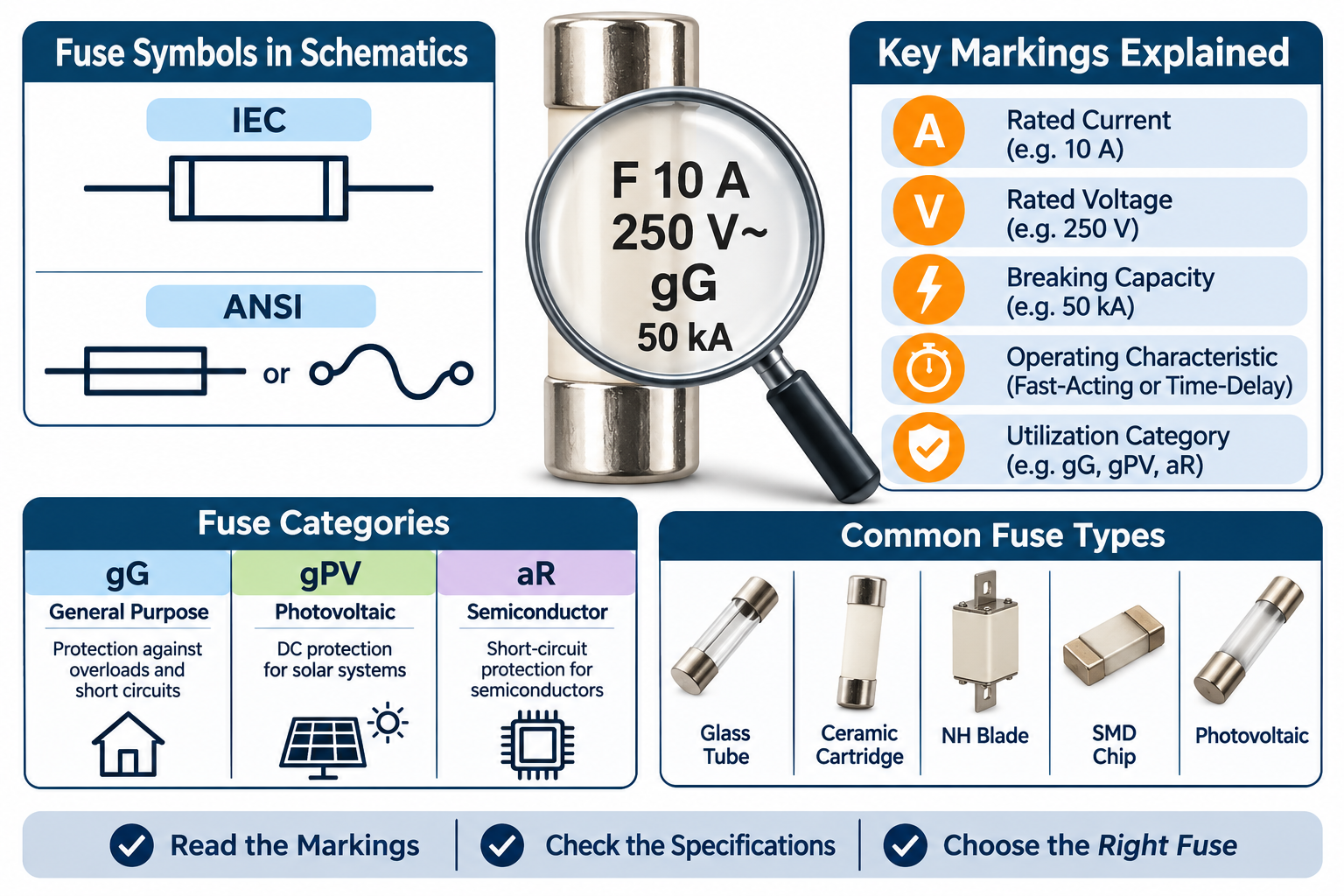
Under IEC 60617, a fuse is generally represented by a rectangular symbol with internal vertical lines near the ends.
The connecting conductors meet the outer edges of the rectangle.
This graphical representation identifies the fuse's function without specifying its physical construction, size, or electrical rating.
IEC symbols are widely used in international electrical engineering documentation, industrial equipment drawings, and electrical control systems.
ANSI Fuse Symbol
ANSI/IEEE Y32.2 includes two commonly recognized fuse symbol representations:
-
A rectangular symbol with a continuous line through its centre.
-
An S-shaped curve with small terminal circles representing the fuse element.
The rectangular representation is frequently found in older North American electrical drawings, while the curved representation provides a more descriptive illustration of the fuse element.
IEC vs. ANSI Fuse Symbols
Although both standards represent the same protective function, their graphical conventions are not identical.
When interpreting electrical schematics, engineers should identify the drafting standard before making assumptions based on the symbol's appearance.
The reference designator also provides useful information:
-
F or FU: Common reference designators for fuses.
-
R: Typically identifies a resistor.
-
Q or CB: Commonly identifies a switching or circuit-breaker device, depending on the drafting convention.
Never rely exclusively on the graphical appearance of a symbol when the applicable drawing standard is unknown.
3. How to Read Fuse Markings on Electrical Schematics
The annotation beside a fuse symbol provides the electrical information needed to identify and specify the protective device.
A typical fuse annotation may include:
-
Reference designator.
-
Operating characteristic.
-
Rated current.
-
Rated voltage.
For example:
F1 T 1.6A 250V
This marking can be interpreted as follows:
-
F1: Identifies the first fuse in the electrical design.
-
T: Indicates a time-delay fuse.
-
1.6A: Specifies the rated current of 1.6 amperes.
-
250V: Indicates a rated voltage of 250 volts.
Understanding the difference between these markings is essential.
Reference Designator
The reference designator identifies a particular component within an electrical circuit.
For example, F1, F2, and F3 may identify three different fuses in the same schematic.
These labels help engineers locate components in circuit diagrams, bills of materials, and maintenance documentation.
The reference designator does not indicate the fuse's operating speed or electrical rating.
Fuse Operating Characteristics
Fuse operating characteristics describe how quickly a fuse responds when excessive current flows through it.
The two commonly used markings are:
-
F – Fast-Acting: Designed to interrupt excessive current quickly. These fuses are suitable for circuits containing components that require rapid overcurrent protection.
-
T – Time-Delay: Designed to tolerate temporary current surges without opening immediately. They are commonly used in circuits with motors, transformers, and other equipment that produces short-duration inrush currents.
Choosing the wrong operating characteristic can result in nuisance fuse operation or insufficient protection.
Rated Current
The current rating, measured in amperes (A), indicates the current a fuse is designed to carry under specified operating conditions.
Common examples include:
-
1A
-
2A
-
5A
-
10A
-
16A
-
32A
-
63A
A fuse's rated current should not be confused with its minimum melting current or its guaranteed operating threshold.
Its actual operating behaviour depends on factors such as current magnitude, duration, ambient temperature, and the fuse's time-current characteristics.
Rated Voltage
The voltage rating indicates the maximum circuit voltage for which the fuse is designed to operate safely under specified conditions.
Common markings include:
-
125V
-
250V
-
500V
-
690V
-
1000V DC
-
1500V DC
The voltage rating is particularly important because a fuse must be capable of safely extinguishing the electrical arc that develops when it interrupts a fault.
A fuse with an adequate current rating but an insufficient voltage rating may fail to interrupt the fault safely.
Always check whether the fuse is rated for AC or DC applications. AC and DC interruption characteristics are different, and a fuse must be suitable for the actual circuit conditions.
4. Understanding Fuse Utilization Categories: gG, gPV and aR
Utilization categories provide additional information about the intended operating conditions and protection capabilities of a fuse.
Under the IEC 60269 series of standards, utilization categories generally consist of two letters.
The first letter describes the fuse's breaking range, while the second identifies its intended application.
Understanding these classifications is especially important in industrial electrical systems, renewable energy installations, and semiconductor protection.
gG – General-Purpose Fuse
The gG utilization category identifies a full-range fuse designed for general-purpose protection.
These fuses provide protection against both overloads and short circuits.
Typical applications include:
-
Electrical distribution systems.
-
Cable and conductor protection.
-
Industrial control panels.
-
General low-voltage electrical installations.
The gG category is commonly used in conventional electrical distribution applications.
gPV – Photovoltaic Fuse
The gPV category is specifically designed for photovoltaic applications and is covered by IEC 60269-6.
Solar PV systems have particular electrical characteristics, including high DC operating voltages and specific fault-current conditions.
Photovoltaic fuses are designed to address the protection requirements of solar strings and arrays.
Typical applications include:
-
Solar panel strings.
-
PV combiner boxes.
-
Solar DC distribution systems.
-
Photovoltaic energy installations.
Using a correctly specified gPV fuse helps provide appropriate overcurrent protection in photovoltaic circuits.
aR – Semiconductor Protection Fuse
The aR utilization category identifies a partial-range fuse designed primarily for short-circuit protection of semiconductor devices.
These fuses are commonly used to protect sensitive electronic components such as:
-
Power semiconductor devices.
-
Thyristors.
-
Rectifiers.
-
Inverters.
-
Power conversion equipment.
Unlike full-range fuses, aR fuses are not intended to provide complete overload protection independently. Additional protection may be required to address overload conditions.
Understanding the Difference
| Fuse Category | Breaking Range | Typical Application |
|---|---|---|
| gG | Full-range | General electrical protection |
| gPV | Full-range | Photovoltaic systems |
| aR | Partial-range | Semiconductor short-circuit protection |
The utilization category should never be overlooked when selecting a replacement fuse. Two fuses with identical current and voltage ratings may have different operating characteristics and application requirements.
5. How to Read Markings on a Physical Fuse
Reading markings directly from a physical fuse is just as important as interpreting its schematic symbol.
Manufacturers typically print or engrave essential electrical specifications on the fuse body, end caps, or identification labels.
Depending on the fuse design and available marking space, these details may include:
Current Rating (A)
The current rating identifies the nominal current capacity of the fuse.
For example, a marking of 20A indicates a rated current of 20 amperes.
Voltage Rating (V)
The voltage marking indicates the rated operating voltage.
For example, 500V AC or 1000V DC identifies the voltage rating and current type for which the fuse is designed.
Breaking Capacity
Breaking capacity, also called interrupting rating, indicates the maximum prospective fault current that a fuse can safely interrupt under its specified test conditions.
It may be expressed in amperes or kiloamperes (kA).
For example, a marking of 50kA indicates a rated breaking capacity of 50,000 amperes under the applicable conditions.
This specification is critical because the prospective short-circuit current in an electrical installation must not exceed the fuse's rated breaking capacity.
Utilization Category
Markings such as gG, gPV, and aR identify the fuse's operating category and intended protection application.
These classifications help determine whether the fuse is appropriate for a particular electrical system.
AC or DC Identification
Physical fuse markings may also specify whether the device is intended for alternating-current (AC) or direct-current (DC) applications.
This distinction is particularly important in solar photovoltaic systems, battery storage installations, electric vehicles, and other DC power applications.
Manufacturer and Certification Information
Depending on the product, additional markings may identify:
-
Manufacturing specifications.
-
Applicable technical standards.
-
Certification or approval marks.
-
Product series or model numbers.
-
Manufacturing batch or traceability codes.
These markings help users verify product identity and check compliance with the relevant application requirements.
6. Common Physical Fuse Types and Their Identification
Fuse symbols do not identify the physical construction of a fuse. The same schematic symbol can represent several different fuse designs.
Physical fuse types are selected according to electrical ratings, installation requirements, breaking capacity, and application.
Common types include:
Glass Tube Fuses
Glass tube fuses feature a cylindrical glass body with metal end caps.
They allow visual inspection of the internal fuse element and are commonly found in electronic equipment and low-power electrical circuits.
Ceramic Cartridge Fuses
Ceramic cartridge fuses use a ceramic body instead of glass.
Their construction can provide greater mechanical strength and support higher electrical ratings and breaking capacities, depending on the design.
They are commonly used in industrial equipment and electrical distribution applications.
NH Blade Fuses
NH fuses are industrial low-voltage fuse links featuring a rectangular body and blade-type electrical contacts.
They are widely used in electrical distribution systems, industrial switchgear, and power protection installations.
SMD Chip Fuses
Surface-mount device (SMD) fuses are compact protective components designed for installation directly onto printed circuit boards.
They are commonly used in consumer electronics, communication equipment, and compact electronic devices.
Photovoltaic Fuses
Photovoltaic fuses are specifically designed for DC protection in solar energy systems.
They are available in different physical sizes and electrical ratings to accommodate various solar installation requirements.
The correct fuse must be selected according to the system voltage, rated current, breaking capacity, and applicable photovoltaic protection requirements.
7. Common Mistakes When Reading Fuse Symbols and Markings
Incorrect interpretation of fuse markings can lead to component mismatches and potentially dangerous electrical faults.
The following mistakes should be avoided.
Confusing F1 with the Fast-Acting Characteristic
F1 identifies a fuse's position in a circuit diagram. It does not automatically mean that the fuse has a fast-acting characteristic.
The separate F marking before a current rating indicates a fast-acting fuse.
Ignoring the Voltage Rating
Selecting a fuse based only on its current rating is insufficient.
The voltage rating must be appropriate for the circuit, and AC/DC compatibility must also be considered.
Overlooking Breaking Capacity
A fuse may have the correct current and voltage ratings but still be unsuitable if its breaking capacity is lower than the prospective short-circuit current.
Always verify the available fault current and the fuse's rated interrupting capability.
Confusing gG and gPV Fuses
Although these fuse categories may have similar physical appearances, they are designed for different protection applications.
A general-purpose fuse should not automatically be considered an acceptable replacement for a photovoltaic fuse.
Ignoring the Time-Current Characteristic
Replacing a time-delay fuse with a fast-acting fuse can result in unnecessary interruptions during normal starting or inrush conditions.
Similarly, installing a time-delay fuse where rapid protection is required may compromise circuit protection.
Selecting a Fuse Based Only on Physical Dimensions
Two fuses may have identical dimensions but completely different electrical specifications.
Always compare the full electrical and utilization specifications rather than relying on physical appearance alone.
8. Practical Checklist for Identifying and Selecting the Correct Fuse
Before installing or replacing a fuse, check the following specifications:
-
Reference designator: Confirm the fuse identification in the electrical schematic.
-
Operating characteristic: Determine whether a fast-acting or time-delay fuse is required.
-
Rated current: Verify the specified current rating and operating conditions.
-
Rated voltage: Confirm that the voltage rating is suitable for the actual AC or DC circuit.
-
Breaking capacity: Ensure that the fuse can safely interrupt the prospective fault current.
-
Utilization category: Check whether gG, gPV, aR, or another category is required.
-
Physical dimensions: Confirm compatibility with the fuse holder or installation.
-
Technical standards: Verify compliance with the relevant IEC or other applicable standards.
-
Technical datasheet: Cross-check the physical markings against the manufacturer's specifications.
-
Application requirements: Confirm that the fuse is suitable for the equipment and operating environment.
Following this checklist helps reduce component selection errors and improves the reliability of electrical protection systems.
9. Frequently Asked Questions About Fuse Symbols and Markings
What does F1 mean on a circuit diagram?
F1 is a reference designator identifying a specific fuse in an electrical circuit. It indicates the component's position in the design rather than its operating characteristic.
What is the difference between IEC and ANSI fuse symbols?
IEC 60617 generally represents a fuse using a rectangular symbol with internal vertical lines near the ends. ANSI/IEEE Y32.2 uses a rectangular symbol with a continuous centre line or an S-shaped curve with terminal circles.
Both represent the same protective function, but their graphical conventions differ.
What does T mean on a fuse?
T indicates a time-delay fuse. It is designed to withstand certain temporary current surges without opening immediately, making it suitable for applications with starting currents or inrush currents.
What does F mean on a fuse?
F indicates a fast-acting fuse. It is designed to respond quickly to excessive current and is commonly used where sensitive components require rapid overcurrent protection.
What does gG mean on a fuse?
gG identifies a full-range general-purpose fuse designed to provide both overload and short-circuit protection.
What does gPV mean on a fuse?
gPV identifies a full-range fuse specifically designed for photovoltaic applications, including solar string and array protection.
What does aR mean on a fuse?
aR identifies a partial-range fuse intended primarily for short-circuit protection of semiconductor devices. Additional protection is required for overload conditions where applicable.
Can the fuse symbol tell me the current and voltage rating?
No. The graphical symbol only indicates the presence and function of a fuse. Current and voltage ratings must be obtained from the schematic annotation, component specifications, physical markings, or technical datasheet.
Why is breaking capacity important when selecting a fuse?
Breaking capacity determines the maximum prospective fault current that a fuse can safely interrupt under specified conditions. An inadequate breaking capacity can result in dangerous failure during a short circuit.
Can two fuses with the same current rating be interchangeable?
Not necessarily. They may have different voltage ratings, breaking capacities, operating characteristics, utilization categories, or physical dimensions. All relevant specifications must be checked before replacement.
Conclusion
Understanding how to read fuse symbols and markings is essential for selecting, identifying, and maintaining the correct electrical protection devices.
Fuse symbols provide information about the position and function of protective devices in electrical schematics, while their annotations and physical markings communicate the specifications required for correct selection.
From current and voltage ratings to operating characteristics, breaking capacity, and utilization categories such as gG, gPV, and aR, every marking plays an important role in determining whether a fuse is suitable for its intended application.
For electrical engineers, technicians, and system designers, the most reliable approach is to evaluate the complete fuse specification rather than focusing on a single marking or physical feature.
By understanding the differences between IEC and ANSI symbols, correctly interpreting fuse annotations, and verifying physical fuse markings against technical datasheets, users can make more informed decisions and help ensure safe, reliable, and effective electrical circuit protection.