 eaton-bussmann-series-photovoltaic-fuses-catalogue-ca135004en.pdf  | [Eaton Bussmann PV Fuses] | 0 kB |
How to Select 1500V DC Protection for PV Systems: Fuse, SPD and Circuit Breaker Coordination
Introduction
As solar photovoltaic (PV) technology continues to develop, 1500V DC systems have become an increasingly popular solution for large-scale solar power plants and utility-scale installations. Compared with traditional 1000V DC systems, 1500V DC architectures can reduce string current, minimize cable losses, decrease the number of system components, and improve overall balance-of-system efficiency.
However, operating at higher DC voltages also introduces additional electrical safety challenges. Selecting the wrong protection device can lead to equipment damage, overheating, electrical faults, or even fire hazards.
A reliable 1500V DC PV protection system requires more than choosing individual components with suitable voltage and current ratings. It requires proper coordination between photovoltaic fuses, surge protective devices (SPDs), and DC circuit breakers.
Each device performs a different protective function:
-
PV fuses: Protect against overcurrent and reverse-current faults.
-
Surge protective devices (SPDs): Protect electrical equipment against transient overvoltages caused by lightning and switching events.
-
DC circuit breakers: Provide overcurrent protection, circuit isolation, and switching functionality where required.
Understanding how these devices work together is essential for designing a safe, reliable, and efficient 1500V DC photovoltaic system.
This guide explains how to select 1500V DC protection devices, the key technical parameters to consider, and how to coordinate fuses, SPDs, and circuit breakers in solar PV applications.
1. Why Is 1500V DC Protection Important in Solar PV Systems?
The transition from 1000V DC to 1500V DC has helped improve the efficiency and economics of large photovoltaic installations.
Higher system voltage allows more PV modules to be connected in series, reducing the number of parallel strings required for a given system capacity. This can reduce cable requirements, installation complexity, and electrical losses.
Nevertheless, higher voltage increases the demands placed on electrical protection equipment.
Unlike AC systems, DC circuits do not naturally pass through zero current during each electrical cycle. Consequently, interrupting DC fault currents can be more challenging because electrical arcs may continue unless the protection device is specifically designed to extinguish them.
A suitable 1500V DC protection system must address several potential risks:
Overcurrent and reverse-current faults: When multiple PV strings are connected in parallel, healthy strings can feed current into a faulty string. This reverse current can damage modules and cables if adequate protection is not provided.
Lightning and switching surges: Transient overvoltages can damage inverters, monitoring equipment, and other sensitive electrical components.
Short-circuit faults: Fault currents must be interrupted safely without exceeding the breaking capacity of the protective device.
Thermal stress: High ambient temperatures, poor electrical connections, and insufficient ventilation can cause excessive heating inside PV combiner boxes.
Electrical isolation: Maintenance personnel need suitable means of disconnecting electrical circuits safely.
For these reasons, fuse, SPD, and circuit breaker selection should be treated as an integrated engineering process.
2. How to Select a 1500V DC PV Fuse
A photovoltaic fuse is one of the most important protection components in a solar power system.
Its primary purpose is to interrupt excessive current caused by reverse-current conditions, short circuits, and other overcurrent faults.
For 1500V DC photovoltaic applications, engineers should generally consider gPV fuse-links designed specifically for solar PV protection.
IEC 60269-6 provides requirements for fuse-links used to protect photovoltaic strings and photovoltaic arrays.
2.1 Check the Maximum DC Operating Voltage
The first step in selecting a 1500V DC PV fuse is verifying its rated DC voltage.
A common mistake is selecting a fuse based only on the nominal system voltage. However, PV module open-circuit voltage increases as temperature decreases.
Therefore, the maximum string voltage must be calculated using the number of modules connected in series, the module's open-circuit voltage, and the applicable temperature correction.
The selected fuse must have a DC voltage rating suitable for the maximum calculated system voltage.
The fuse holder must also have a compatible voltage rating.
Important: A fuse rated for 1000V DC should not be used in a 1500V DC system simply because its current rating is suitable.
2.2 Determine the Correct Fuse Current Rating
The fuse rated current must be selected according to the expected operating current and the applicable electrical design requirements.
Engineers should consider:
-
PV module short-circuit current (Isc).
-
Expected continuous string current.
-
Applicable design and safety factors.
-
Maximum series fuse rating specified by the PV module manufacturer.
-
Ambient temperature and installation conditions.
-
Fuse-holder current rating.
The selected fuse must withstand normal operating conditions without unnecessary operation while providing effective protection under fault conditions.
An oversized fuse may fail to protect the PV circuit adequately, while an undersized fuse can cause unnecessary interruptions.
2.3 Verify DC Breaking Capacity
Breaking capacity is another essential parameter when selecting a 1500V DC fuse.
It represents the maximum fault current that the fuse can safely interrupt under its specified operating conditions.
In a photovoltaic system, available fault current depends on the number of parallel strings and the electrical characteristics of the installation.
The fuse breaking capacity must be sufficient for the prospective fault current at the actual system voltage.
Never assume that a fuse suitable for an AC application or a lower-voltage DC application will automatically provide adequate protection in a 1500V DC circuit.
2.4 Evaluate Fuse Characteristics and Thermal Performance
In addition to voltage and current ratings, engineers should evaluate the fuse's time-current characteristics.
Important parameters include:
-
Pre-arcing I²t.
-
Total clearing I²t.
-
Time-current operating characteristics.
-
Temperature derating.
-
Power dissipation.
-
Thermal stability under continuous operation.
These parameters are particularly important when coordinating fuses with cables, semiconductor equipment, and other protective devices.
2.5 Select the Appropriate Fuse Size and Format
The physical dimensions and installation format of a PV fuse also influence system design.
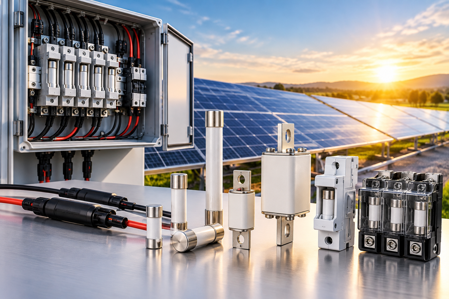
Common 1500V DC PV fuse formats include:
-
10×85 mm cylindrical fuse-links.
-
14×85 mm cylindrical fuse-links.
-
22×58 mm cylindrical fuse-links.
-
NH-style photovoltaic fuse-links.
Compact cylindrical fuse formats are often suitable for space-efficient combiner box designs, while larger fuse formats may be preferred for higher-current applications and particular mounting requirements.
The final choice should consider current rating, electrical performance, installation space, terminal configuration, and maintenance requirements.
3. Why 1500V DC PV Fuse Holders Matter
Selecting the correct fuse is only part of the protection process. The fuse holder must also be suitable for the electrical and environmental conditions of the PV installation.
An incorrectly selected fuse holder can cause excessive contact resistance, temperature rise, and unreliable electrical connections.
When selecting a 1500V DC PV fuse holder, consider the following factors:
Voltage rating: The holder must be suitable for the maximum DC system voltage.
Current rating: Its rated current must match the intended fuse and application.
Contact resistance: Reliable electrical contacts help minimize power losses and overheating.
Creepage and clearance distances: Appropriate insulation distances are essential for high-voltage applications.
Terminal design: Connections must accommodate the specified conductor sizes and installation requirements.
Temperature performance: The holder must operate reliably under the expected ambient and enclosure temperatures.
Mechanical compatibility: The fuse dimensions, mounting arrangement, and terminal design must match.
Thermal management is especially important in densely arranged PV combiner boxes, where several fuse holders operate close together.
Engineers should consider the combined heat generated by adjacent components rather than evaluating each fuse holder independently.
4. How to Select a 1500V DC Surge Protective Device (SPD)
Surge protective devices are designed to protect PV system components against transient overvoltages.
Lightning strikes, induced lightning surges, and switching operations can generate voltage transients that exceed the withstand capability of sensitive electrical equipment.
Without suitable surge protection, these events may damage:
-
Solar inverters.
-
PV monitoring equipment.
-
DC distribution equipment.
-
Communication interfaces.
-
Electrical control systems.
For photovoltaic applications up to 1500V DC, IEC 61643-31 provides requirements and testing methods for DC-side surge protective devices.
4.1 Check the Maximum Continuous Operating Voltage (Ucpv)
One of the most important SPD selection parameters is Ucpv, the maximum continuous operating voltage for PV applications.
The SPD's Ucpv must be compatible with the maximum voltage that can occur across the PV array under the specified operating conditions.
If the selected Ucpv is too low, the SPD may operate continuously under normal system conditions, potentially causing premature degradation or failure.
For this reason, engineers should calculate the maximum PV string voltage before selecting the SPD.
4.2 Choose the Correct SPD Type
The appropriate SPD type depends on the lightning protection requirements and installation characteristics.
Type 1 PV SPD
Type 1 protection is intended for installations where partial lightning current may enter the electrical system, particularly where an external lightning protection system creates a relevant risk of direct lightning current entering the PV installation.
Type 2 PV SPD
Type 2 protection is generally used to limit induced lightning surges and switching overvoltages.
It is commonly considered for PV combiner boxes and inverter DC inputs where the installation's lightning risk assessment supports this arrangement.
Type 1+2 PV SPD
Combined Type 1+2 devices provide both Type 1 and Type 2 surge protection functions.
They may be appropriate where the installation requires both protection against partial lightning currents and protection against induced surges.
The final SPD configuration should be determined by the lightning risk assessment, electrical installation design, and applicable local standards.
4.3 Evaluate Discharge Current Ratings
SPD selection should not be based only on a headline discharge-current value.
Engineers should evaluate several parameters:
-
In: Nominal discharge current.
-
Imax: Maximum discharge current.
-
Iimp: Impulse current, where applicable.
-
Up: Voltage protection level.
-
Ucpv: Maximum continuous operating voltage for PV applications.
These values describe different aspects of SPD performance.
For example, a higher discharge-current rating does not automatically mean that the SPD provides better protection for a particular inverter.
The voltage protection level must also be compatible with the withstand voltage of the protected equipment.
4.4 Consider SPD Installation Location
The installation location influences the SPD protection strategy.
Depending on system configuration and cable lengths, SPDs may be installed at:
-
PV array or combiner box DC inputs.
-
DC distribution panels.
-
Inverter DC terminals.
Long cable runs between the PV array and inverter can influence the effectiveness of surge protection.
Engineers should consider cable routing, conductor lengths, grounding arrangements, and the coordination of multiple SPDs.
Correct installation is just as important as selecting the correct SPD specifications.
5. How to Select a 1500V DC Circuit Breaker
DC circuit breakers provide overcurrent protection and switching functionality in photovoltaic and DC distribution systems.
They are commonly used in DC branch circuits, distribution panels, inverter connections, and energy storage applications.
Unlike fuses, circuit breakers can generally be reset after an interruption, provided the cause of the fault has been identified and corrected.
However, not all circuit breakers are suitable for high-voltage DC applications.
5.1 Verify the DC Voltage Rating
The circuit breaker's rated DC voltage must be suitable for the maximum system voltage.
An AC voltage rating cannot automatically be applied to a DC circuit.
DC interruption is more challenging because the current does not naturally cross zero during normal operation.
Therefore, the selected breaker must have an appropriate certified DC voltage rating and interruption capability.
5.2 Check the Breaking Capacity
The circuit breaker's breaking capacity must be greater than or equal to the prospective short-circuit current at the installation point, considering the applicable rating conditions.
An inadequate breaking capacity can result in failed fault interruption and serious equipment damage.
Engineers should assess the available fault current, system configuration, and the electrical characteristics of the connected equipment.
5.3 Understand Pole Configuration
Pole configuration is particularly important in 1500V DC applications.
Some DC circuit breakers require multiple poles connected in series to achieve the specified voltage and arc-interruption performance.
The manufacturer's approved wiring diagram must be followed precisely.
Engineers should verify:
-
Number of poles required.
-
Approved series connection arrangement.
-
Polarity requirements, where applicable.
-
Rated DC voltage for the specified configuration.
-
Short-circuit breaking capacity.
-
Isolation capability.
Never assume that a standard AC miniature circuit breaker can safely interrupt a 1500V DC circuit.
5.4 Choose Between DC MCB and DC MCCB
Two common circuit breaker categories are miniature circuit breakers (MCBs) and molded-case circuit breakers (MCCBs).
DC MCB
DC MCBs are generally used for lower-current DC branch circuits and applications where compact installation is important.
Typical applications include smaller DC distribution circuits and selected auxiliary circuits.
DC MCCB
DC MCCBs are commonly used for higher-current applications and DC distribution systems.
Depending on the design, they may provide adjustable protection settings, higher breaking capacities, and additional installation flexibility.
The choice between an MCB and MCCB should depend on the required current rating, fault level, protection settings, installation environment, and system architecture.
IEC 60947-2:2024 is an important reference for circuit breakers within its scope, including relevant DC applications up to 1500V.
6. How to Coordinate PV Fuses, SPDs, and DC Circuit Breakers
Selecting individual protective devices correctly does not guarantee that the entire PV protection system will operate safely.
The devices must work together without interfering with one another.
This is known as protection coordination.
In a 1500V DC PV system, each protective device has a different responsibility.
| Protection Device | Main Function | Key Selection Parameters | Typical Application |
|---|---|---|---|
| gPV Fuse | Overcurrent and reverse-current protection | Voltage, current, breaking capacity, I²t | PV strings and combiner boxes |
| PV Fuse Holder | Safe fuse mounting and current conduction | Voltage, current, temperature, terminals | Combiner boxes and DC panels |
| DC SPD | Transient overvoltage protection | Ucpv, SPD type, In, Imax, Iimp, Up | PV arrays and inverter DC inputs |
| DC MCB | Branch circuit protection and switching | Voltage, current, poles, breaking capacity | DC branch circuits |
| DC MCCB | Higher-current protection and switching | Voltage, current, breaking capacity, trip settings | DC distribution and inverter feeders |
6.1 Coordinate Fuse and Circuit Breaker Protection
Fuses and circuit breakers may both provide overcurrent protection, but their operating characteristics are different.
A fuse typically interrupts a fault by melting its internal element, while a circuit breaker uses a mechanical or electronic tripping mechanism.
When both devices are installed in the same protection architecture, engineers must evaluate their time-current characteristics.
Important considerations include:
-
Prospective short-circuit current.
-
Fuse pre-arcing and total clearing I²t.
-
Circuit breaker trip characteristics.
-
Cable thermal withstand.
-
Equipment short-circuit withstand.
-
Selectivity between upstream and downstream devices.
The objective is to ensure that the protective device closest to the fault operates first whenever selective coordination is required and technically achievable.
This helps isolate the affected circuit while maintaining the operation of healthy sections of the PV installation.
6.2 Coordinate SPD Protection with Overcurrent Devices
SPDs must also be coordinated with their associated overcurrent protection.
During a severe surge event or at the end of the SPD's service life, the SPD may experience conditions requiring disconnection from the circuit.
The SPD manufacturer's specified backup protection requirements must therefore be followed.
Engineers should check:
-
Maximum permitted backup fuse or circuit breaker rating.
-
Short-circuit current withstand.
-
SPD disconnection mechanism.
-
Connection arrangement.
-
Protective conductor routing.
-
Coordination with upstream protection.
An incorrectly sized backup protective device may compromise SPD safety or prevent the protection system from operating as intended.
6.3 Ensure Proper System Isolation
Isolation is another important part of PV protection coordination.
Maintenance personnel must be able to disconnect the relevant DC circuits using devices suitable for the intended isolation function.
A fuse, circuit breaker, or SPD should not automatically be assumed to provide safe isolation simply because it is installed in the DC circuit.
The isolation function must be explicitly supported by the device's rating, certification, and application instructions.
6.4 Consider the Complete PV Protection Architecture
Protection coordination should be evaluated across the entire electrical system rather than at a single component level.
For example, a typical utility-scale PV installation may include:
-
PV modules connected in series to form strings.
-
String fuses protecting against reverse-current faults where required.
-
Combiner boxes collecting parallel PV strings.
-
DC SPDs providing transient overvoltage protection.
-
DC circuit breakers or isolating devices providing the required distribution and switching functions.
-
Inverter DC inputs receiving power from the PV array.
The exact arrangement depends on system topology, inverter requirements, applicable standards, and the electrical protection study.
The goal is to achieve reliable fault interruption, effective surge protection, and safe isolation without unnecessary protection-device interactions.
7. Common Mistakes When Selecting 1500V DC PV Protection
Even experienced engineers can overlook important details when specifying high-voltage PV protection components.
The following mistakes should be avoided.
Mistake 1: Selecting Devices Based Only on Nominal Voltage
Using the nominal system voltage instead of the maximum calculated PV voltage can result in insufficient voltage protection.
Always account for the increase in module open-circuit voltage at low temperatures.
Mistake 2: Selecting a PV Fuse Only by Current Rating
A suitable fuse must meet several requirements, including DC voltage rating, gPV utilization category, breaking capacity, time-current characteristics, and thermal performance.
Ampere rating alone is insufficient.
Mistake 3: Ignoring Fuse Holder Temperature Rise
An unsuitable fuse holder or poor electrical connection can create excessive heat.
This is particularly problematic in compact combiner boxes with limited ventilation.
Select compatible fuse holders and verify their thermal performance under actual installation conditions.
Mistake 4: Choosing an SPD Only by Its kA Rating
Discharge current is only one part of SPD performance.
Ucpv, SPD type, voltage protection level, short-circuit withstand, and backup protection requirements must also be evaluated.
Mistake 5: Using AC Circuit Breakers in DC Applications Without Verification
AC and DC interruption requirements are different.
Always verify the breaker's certified DC rating, pole arrangement, and breaking capacity.
Mistake 6: Ignoring Coordination Between Protective Devices
Installing correctly rated components does not automatically guarantee selective protection.
Fuse characteristics, circuit breaker trip settings, SPD backup protection, and equipment withstand must be evaluated together.
8. Practical Checklist for Selecting a 1500V DC PV Protection System
Before specifying protection devices for a photovoltaic installation, engineers should collect the relevant electrical and environmental information.
The following checklist can help simplify the selection process.
System electrical parameters
-
Maximum DC operating voltage.
-
Maximum PV string open-circuit voltage.
-
Number of modules connected in series.
-
Number of parallel strings.
-
Normal operating current.
-
Prospective fault current.
PV fuse requirements
-
Required gPV fuse utilization category.
-
Rated voltage and current.
-
Maximum series fuse rating of the PV module.
-
DC breaking capacity.
-
Fuse dimensions and mounting arrangement.
-
Temperature derating and I²t characteristics.
SPD requirements
-
Required SPD type.
-
Maximum continuous operating voltage (Ucpv).
-
Nominal discharge current (In).
-
Maximum discharge current (Imax).
-
Impulse current (Iimp), where applicable.
-
Voltage protection level (Up).
-
Backup protection requirements.
Circuit breaker requirements
-
DC rated voltage.
-
Rated current.
-
Breaking capacity.
-
Required pole configuration.
-
Trip characteristics or settings.
-
Isolation requirements.
-
Approved connection arrangement.
Installation and environmental conditions
-
Ambient temperature.
-
Enclosure temperature.
-
Installation altitude, where relevant.
-
Ventilation and heat dissipation.
-
Cable size and terminal configuration.
-
Grounding and lightning protection arrangement.
-
Applicable IEC, UL, and local regulatory requirements.
Collecting this information before selecting components helps reduce specification errors and improves overall system reliability.
9. Why Proper Protection Coordination Improves PV System Reliability
A well-designed 1500V DC protection system provides several important benefits.
Improved electrical safety: Correctly selected fuses and circuit breakers help interrupt overcurrent and short-circuit faults before they cause extensive damage.
Better equipment protection: Properly coordinated SPDs reduce the risk of transient overvoltages damaging sensitive electrical equipment.
Reduced downtime: Effective protection selectivity can isolate faulty circuits while allowing unaffected sections of the installation to continue operating.
Improved thermal performance: Compatible fuse links and holders help reduce excessive contact resistance and unnecessary heat generation.
Lower maintenance costs: Appropriate device selection can reduce premature failures, unexpected interruptions, and equipment replacement costs.
Greater system reliability: Coordinated protection ensures that different devices perform their intended functions under normal operating and fault conditions.
For utility-scale solar installations, these benefits contribute to more stable power generation and improved long-term operating performance.
10. Conclusion: Building a Reliable 1500V DC PV Protection System
Selecting 1500V DC protection for PV systems requires a coordinated approach to electrical safety, overcurrent protection, surge protection, and circuit isolation.
A suitable gPV fuse protects PV strings against reverse-current and overcurrent faults. A properly selected fuse holder ensures reliable electrical connections and thermal performance. A PV DC SPD protects sensitive equipment against transient overvoltages, while a correctly rated DC circuit breaker provides the required switching and overcurrent protection functions.
However, the most important consideration is how these devices work together.
Engineers must evaluate maximum system voltage, operating current, prospective fault current, breaking capacity, temperature conditions, and protection coordination before finalizing a design.
By following the relevant standards and manufacturer specifications, solar system designers can develop a reliable 1500V DC protection architecture that improves equipment safety, minimizes downtime, and supports the long-term performance of photovoltaic installations.
The key to effective 1500V DC PV protection is not simply selecting the right fuse, SPD, or circuit breaker individually. It is ensuring that every protection device performs its intended function as part of one coordinated electrical protection system.
Frequently Asked Questions (FAQs)
1. What protection devices are required in a 1500V DC PV system?
A typical 1500V DC PV protection architecture may include gPV fuses, compatible fuse holders, DC surge protective devices, and DC circuit breakers or isolating devices. The exact configuration depends on the PV system design, inverter requirements, fault analysis, and applicable regulations.
2. What type of fuse is used in a 1500V DC solar system?
A gPV fuse designed for photovoltaic applications is generally used for PV string and array overcurrent protection. It should have a suitable DC voltage rating, current rating, breaking capacity, and utilization category in accordance with the system design.
3. Can a 1000V DC fuse be used in a 1500V DC PV system?
No, a 1000V DC fuse should not be used where the maximum calculated system voltage exceeds its rated voltage. The fuse link and fuse holder must both be suitable for the actual maximum DC voltage.
4. What is the difference between a PV fuse and a DC circuit breaker?
A PV fuse provides overcurrent protection by melting its internal element when current exceeds its operating characteristics. A DC circuit breaker interrupts excessive current through a tripping mechanism and may also provide switching and resettable protection functions.
Both devices have different operating characteristics and should not be considered automatically interchangeable.
5. How do I select a 1500V DC SPD for solar PV?
Start by calculating the maximum PV array voltage and selecting an SPD with a suitable Ucpv rating. Then evaluate the required SPD type, nominal and maximum discharge currents, impulse current where applicable, voltage protection level, short-circuit withstand, and backup protection requirements.
6. What is the difference between Type 1 and Type 2 PV SPDs?
Type 1 SPDs are designed to handle partial lightning currents where the installation's lightning protection arrangement creates this requirement. Type 2 SPDs are designed primarily to limit induced lightning surges and switching overvoltages. Type 1+2 devices combine both protection functions.
7. Why is circuit breaker pole configuration important in 1500V DC applications?
Some DC circuit breakers require multiple poles connected in series to achieve their specified voltage rating and interruption performance. Incorrect pole connections can compromise arc extinction and safe fault interruption. Always follow the manufacturer's approved DC wiring diagram.
8. Which standards apply to 1500V DC PV protection?
Important international references include:
-
IEC 60269-6 for photovoltaic fuse-links.
-
IEC 61643-31 for surge protective devices on the DC side of photovoltaic installations.
-
IEC 60947-2 for applicable low-voltage circuit breakers, including relevant DC applications.
Additional installation and safety requirements depend on the project location and applicable national electrical regulations.
9. Why is protection coordination important in a solar PV system?
Protection coordination ensures that fuses, SPDs, and circuit breakers perform their intended functions without interfering with one another. Proper coordination helps isolate faults, protect sensitive equipment, reduce unnecessary interruptions, and improve overall system reliability.
10. What information is needed to select 1500V DC protection devices?
The main information includes maximum DC voltage, PV string current, prospective fault current, number of parallel strings, fuse requirements, SPD type, circuit breaker specifications, ambient temperature, installation arrangement, and required certification.